 |
Roberts R200 - U.K. 1960 |
|
 Description
 |
Click to enlarge

|
Descrizione Schema elettrico |
|||
|
|
|||||
 |
 |
 |
 |
||
 |
 |
 |
 |
||
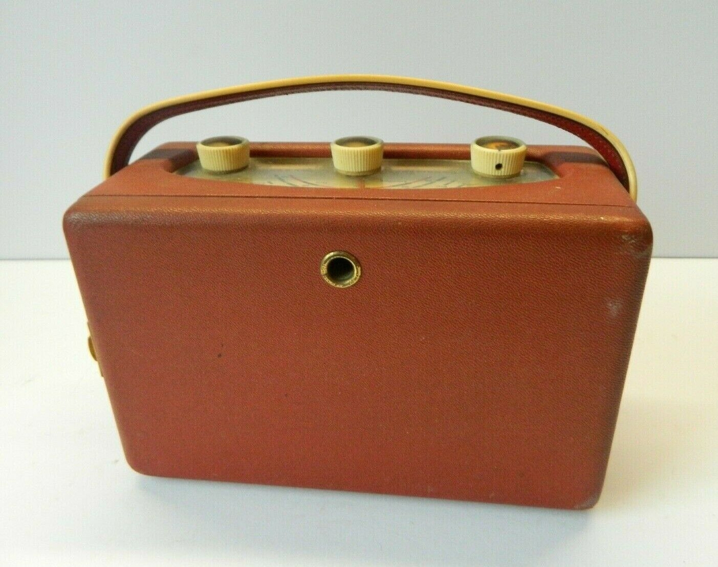
 La Roberts R200 fu il secondo modello di radio a
transistor prodotto dalla ditta inglese Roberts Radio Co. Ltd. e
presentata nel 1960. Come per la precedente
RT.1,
la R200 era un apparecchio robusto ed elegante, realizzato senza pretese
di miniaturizzazione. La radio infatti utilizzava lo stesso elegante
mobiletto in legno ricoperto in finta pelle di vari colori già
ampiamente sperimentato nei precedenti apparecchi portatili a valvole
tipo R55
e
R66 e usato anche per la RT1,
la prima radio
a transistor della Roberts.
La Roberts R200 fu il secondo modello di radio a
transistor prodotto dalla ditta inglese Roberts Radio Co. Ltd. e
presentata nel 1960. Come per la precedente
RT.1,
la R200 era un apparecchio robusto ed elegante, realizzato senza pretese
di miniaturizzazione. La radio infatti utilizzava lo stesso elegante
mobiletto in legno ricoperto in finta pelle di vari colori già
ampiamente sperimentato nei precedenti apparecchi portatili a valvole
tipo R55
e
R66 e usato anche per la RT1,
la prima radio
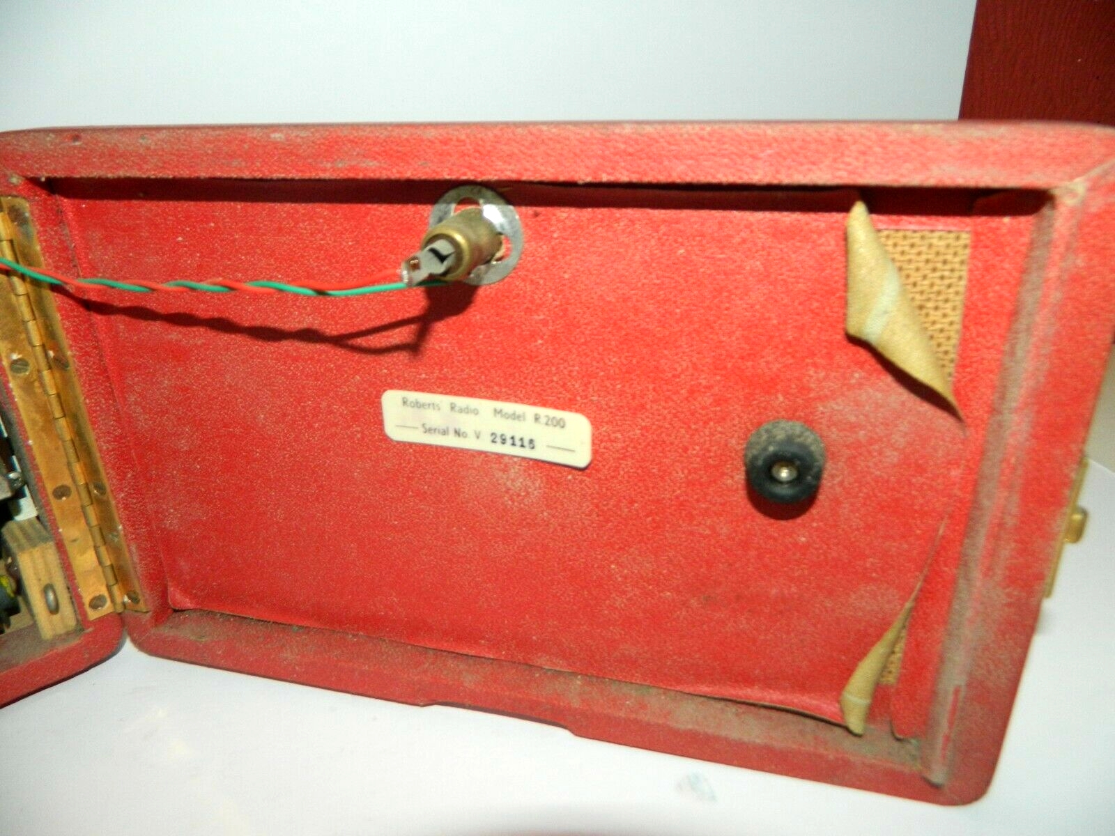
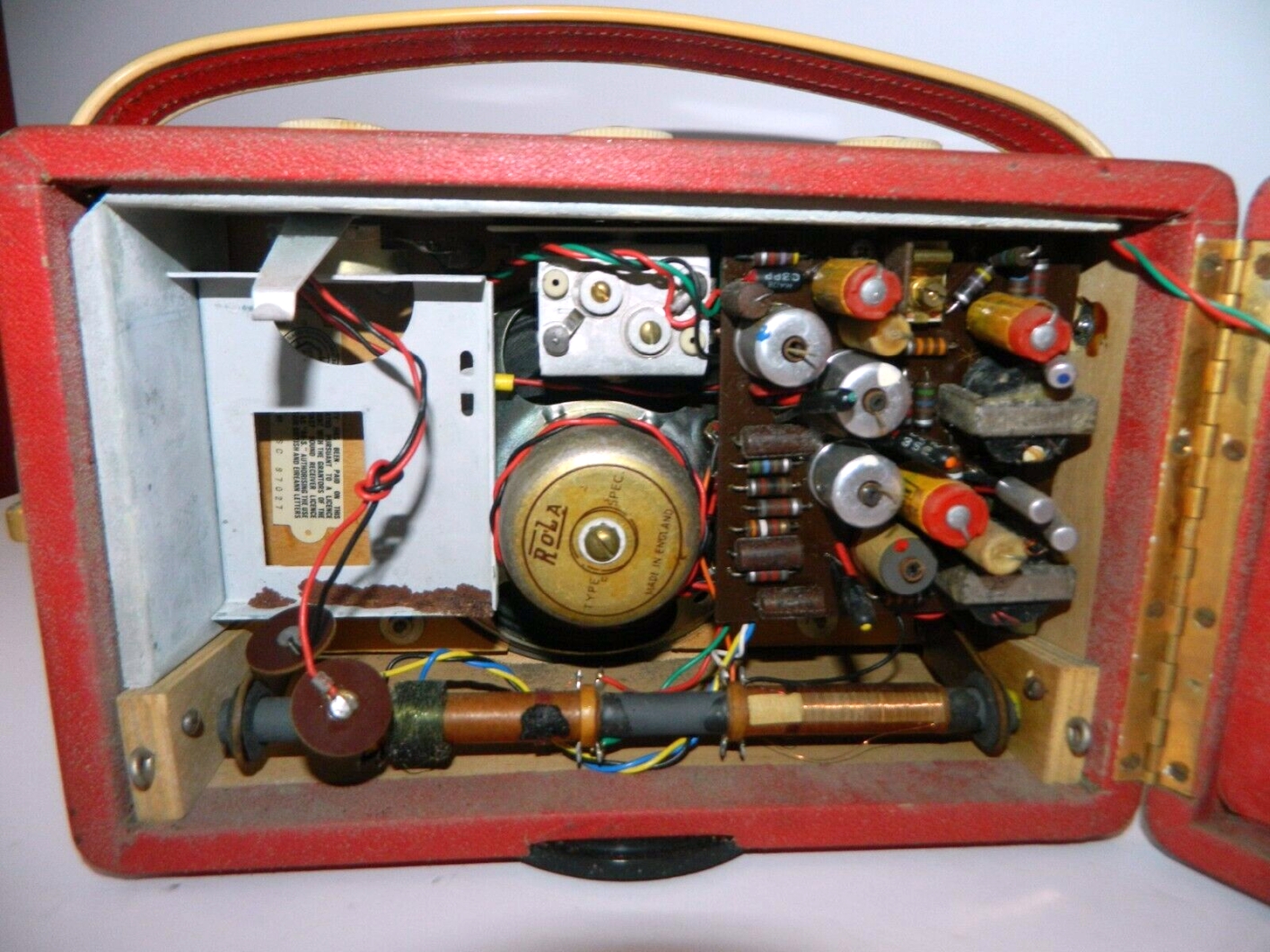
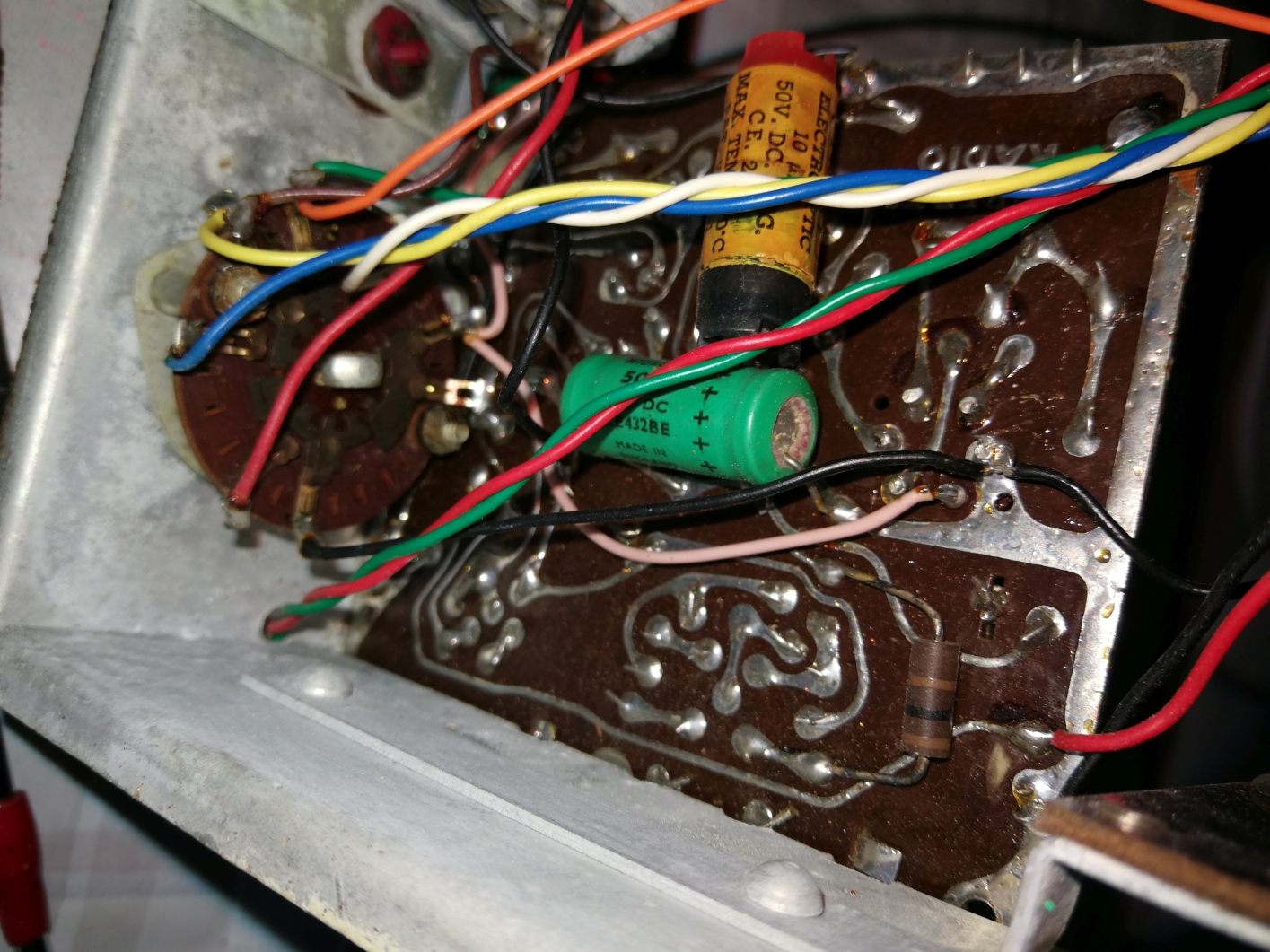
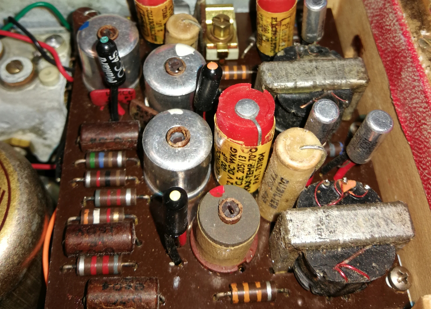
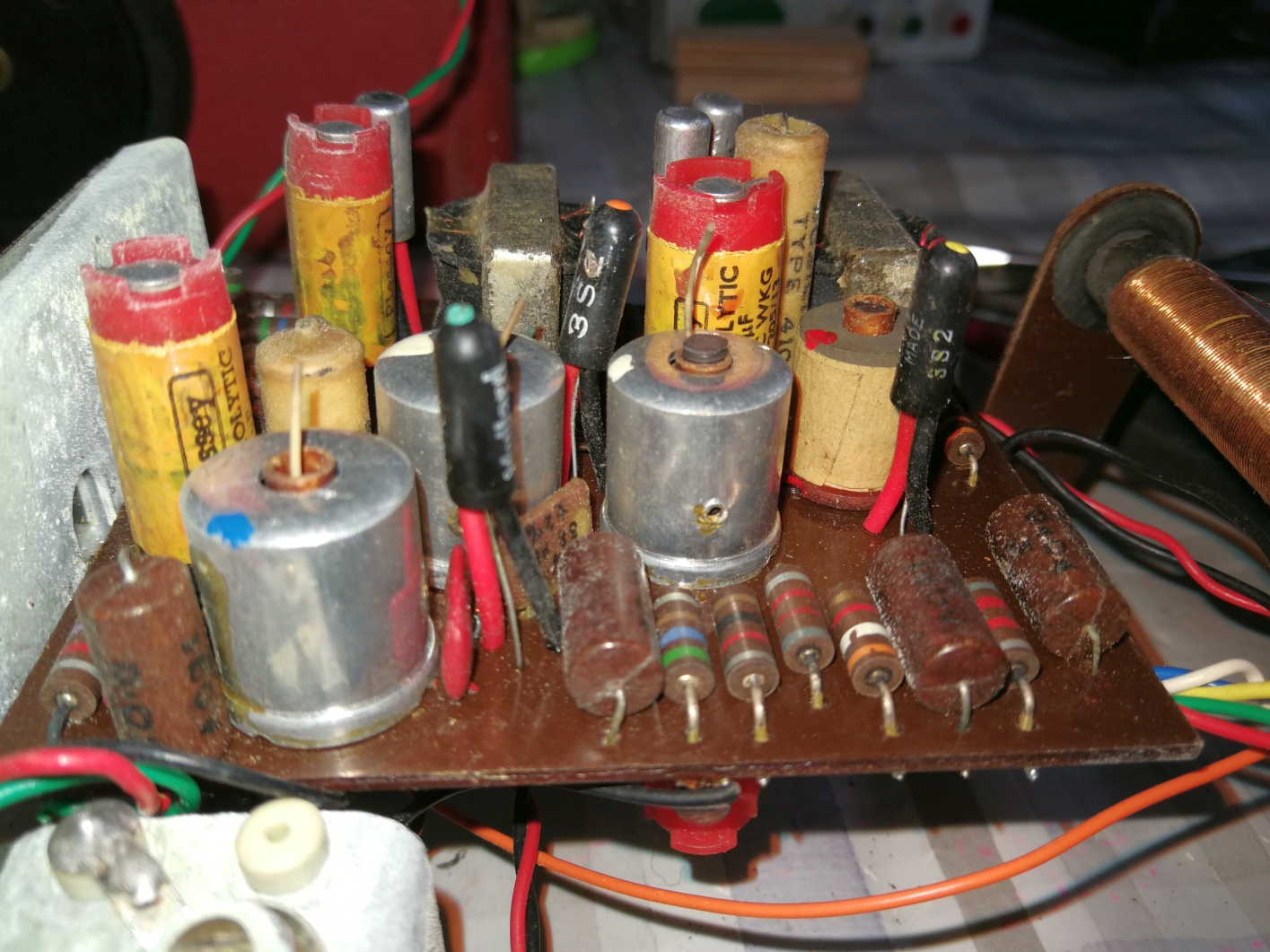
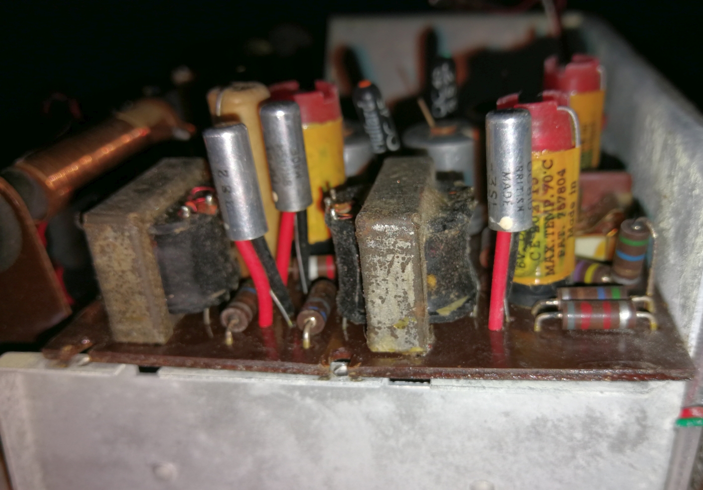
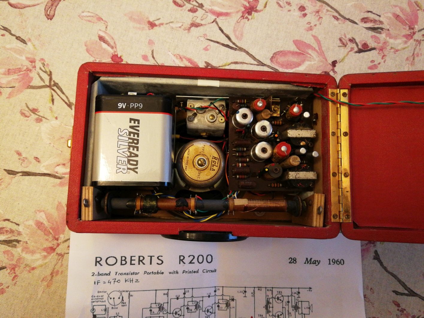
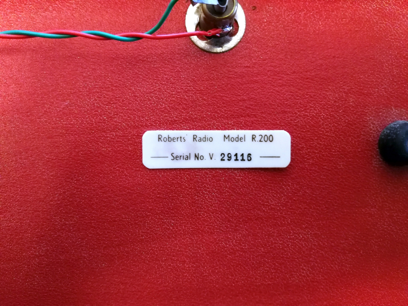
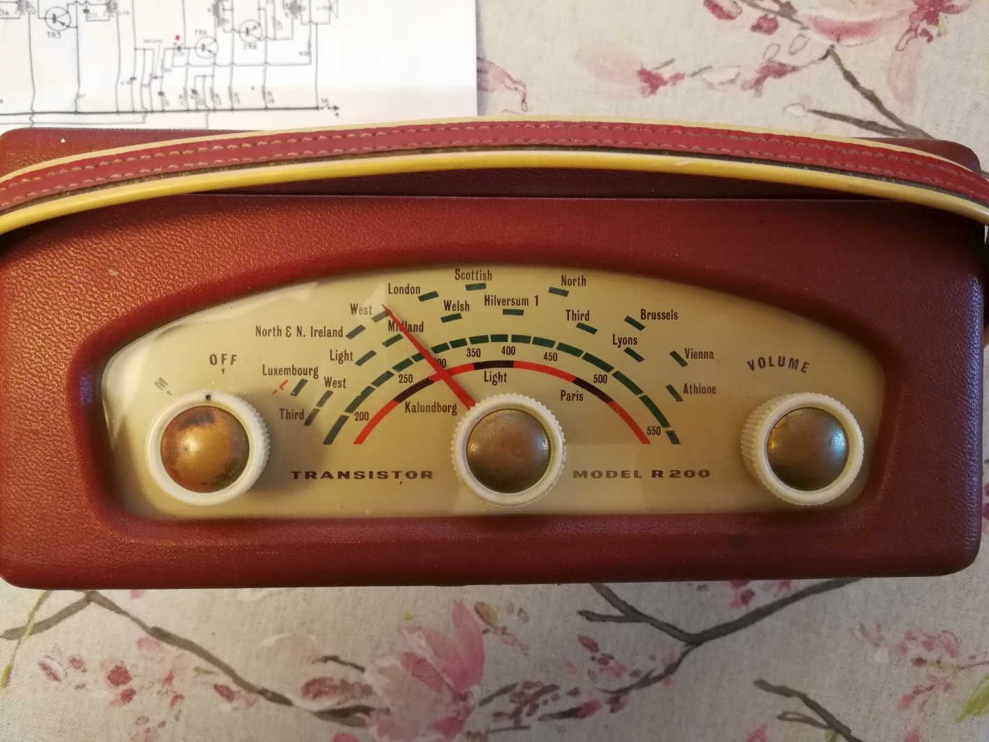
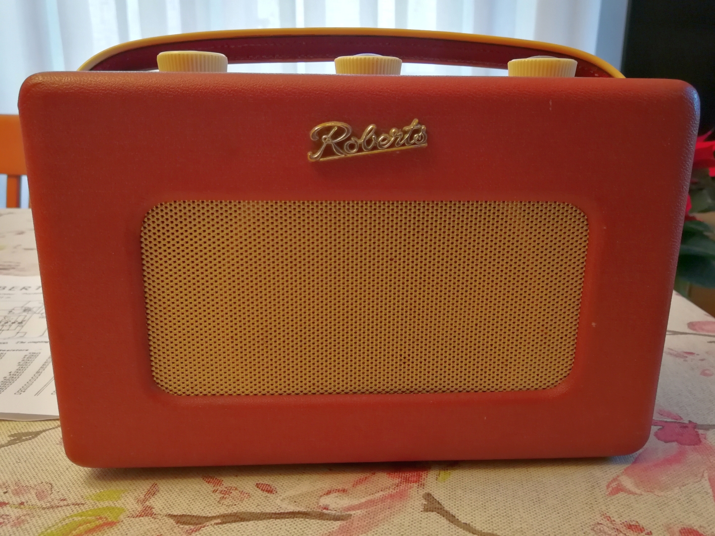
a transistor della Roberts.Il circuito elettrico adottato dalla Roberts era classico, impiegava la serie di sei transistor PNP al germanio con sigla OC prodotti dalla Mullard (OC44, OC45, OC45, OC78D, OC78 e OC78). I transistor dello stadio audio dalla matricola 12962 divennero OC81D, OC81 e OC81 (come nell'esemplare matricola 29116 illustrato in questa pagina). Dopo la matricola 70000 invece la Roberts impiegò la nuova serie della Mullard siglata AF117, AF117, AF117, OC81D, OC81 e OC81. Il circuito del ricevitore era realizzato con un circuito stampato, tecnica abbastanza innovativa per l'epoca e che del resto era stata già adottata anche nel modello RT1. La ricezione delle Onde Medie (539 - 1594 KHz) e delle Lunghe (152 - 265 KHz) avveniva tramite un'antenna interna avvolta su un lungo nucleo in ferrite, la radio disponeva un buon circuito amplificatore a Radio Frequenza e di un doppio stadio a Media Frequenza risonante a 470 KHz. Come per la RT1, per sfruttare al meglio la direzionalità dell'antenna, la Roberts R200 era dotata alla base di un disco di plastica girevole che permetteva l'agevole rotazione del ricevitore in modo da captare meglio il segnale. Per l'eventuale utilizzo del ricevitore a bordo di un'auto, nel pannello posteriore della radio era prevista una presa d'antenna del tipo autoradio. L'alimentazione era fornita da una grossa batteria da 9 V tipo PP9 che assicurava una lunga autonomia, e la resa acustica dell'R200 era buona sia per merito del mobiletto in legno che dell'altoparlante Rola da cinque pollici (12.7 cm) di diametro. Le dimensioni della R200 erano: 22 x 14 x 10 cm e il prezzo di vendita in Inghilterra nel febbraio 1960 (tasse escluse) era di 14 sterline compresa la batteria da 9 V. IK3HIA © 2023. |
|||||
 |
 |
 |
 |
||
|
The Roberts R200 was the second model of
transistor radio produced by the English company Roberts Radio Co. Ltd.
and presented in 1960. Like the previous
RT.1,
the R200 was a robust and elegant device, made without pretensions of
miniaturization. In fact, the radio used the same elegant wooden cabinet
covered in imitation leather of various colors already widely tested in
the previous portable valve devices type
R55
and
R66
and also used for the RT1, the first transistor radio by Roberts. The electrical circuit adopted by Roberts was classic, it used the series of six germanium PNP transistors with the initials OC produced by Mullard (OC44, OC45, OC45, OC78D, OC78 and OC78). The transistors of the audio stage from serial number 12962 became OC81D, OC81 and OC81 (as in the specimen serial number 29116 illustrated on this page). After serial number 70000, Roberts instead used the new Mullard series labeled AF117, AF117, AF117, OC81D, OC81 and OC81. The receiver circuit was made with a printed circuit, a fairly innovative technique for the time and which had also already been adopted in the RT1 model. The reception of Medium Waves (539 - 1594 KHz) and Long Waves (152 - 265 KHz) occurred via an internal antenna wound on a long ferrite core, the radio had a good Radio Frequency amplifier circuit and a double Medium Frequency stage resonant at 470 KHz. As for the RT1, to make the most of the directionality of the antenna, the Roberts R200 was equipped at the base with a rotating plastic disk that allowed the easy rotation of the receiver in order to better capture the signal. For possible use of the receiver on board a car, a car radio type antenna socket was provided on the rear panel of the radio. Power was supplied by a large 9 V PP9 battery that ensured a long autonomy, and the acoustic performance of the R200 was good both thanks to the wooden cabinet and the five-inch (12.7 cm) diameter Rola speaker. The dimensions of the R200 were: 22 x 14 x 10 cm and the selling price in England in February 1960 (excluding taxes) was 14 pounds including the 9 V battery. IK3HIA © 2023. |
|||||
|
Immagini riprese
dopo il restauro |
|||||
 |
 |
 |
 |
||
 |
 |
 |
 |
||
|
Back to the top of the page
|
|||||
|
|
Return to: IK3HIA home page |
|
Return to: Roberts Radio page |
|
Return to: Transistor Radio |