 |
ROBERTS R66 U.K. 1956 |
|
|
|
ROBERTS R66 U.K. 1956 |
|
|
|
|||||
|
|
Description Restoration Schematics |
 |
Descrizione Restauro Schemi |
|
|
|
|
|||||
 |
 |
 |
 |
||
 |
 |
 |
 |
||
 |
 |
 |
 |
||
 Roberts
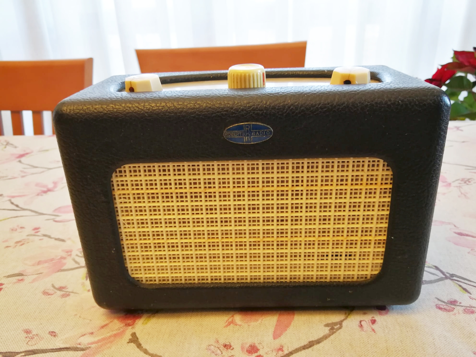
R66 - Great Britain 1956. Roberts
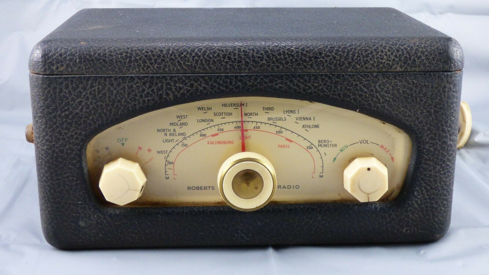
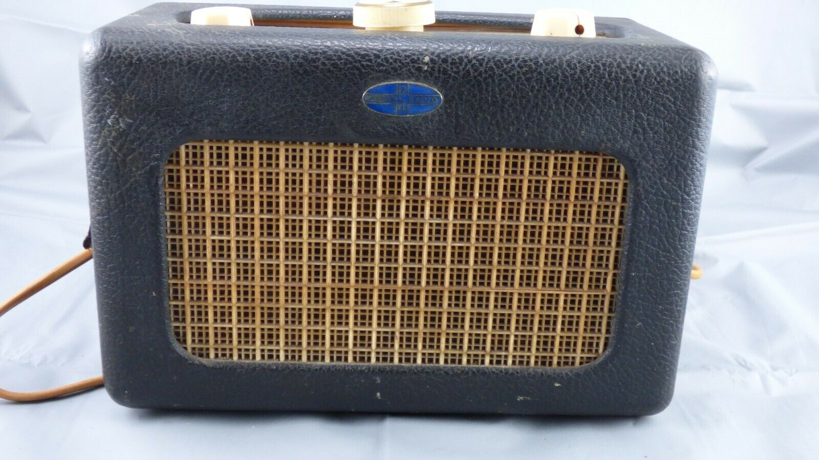
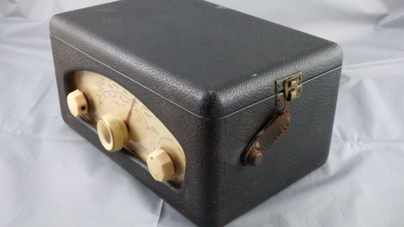
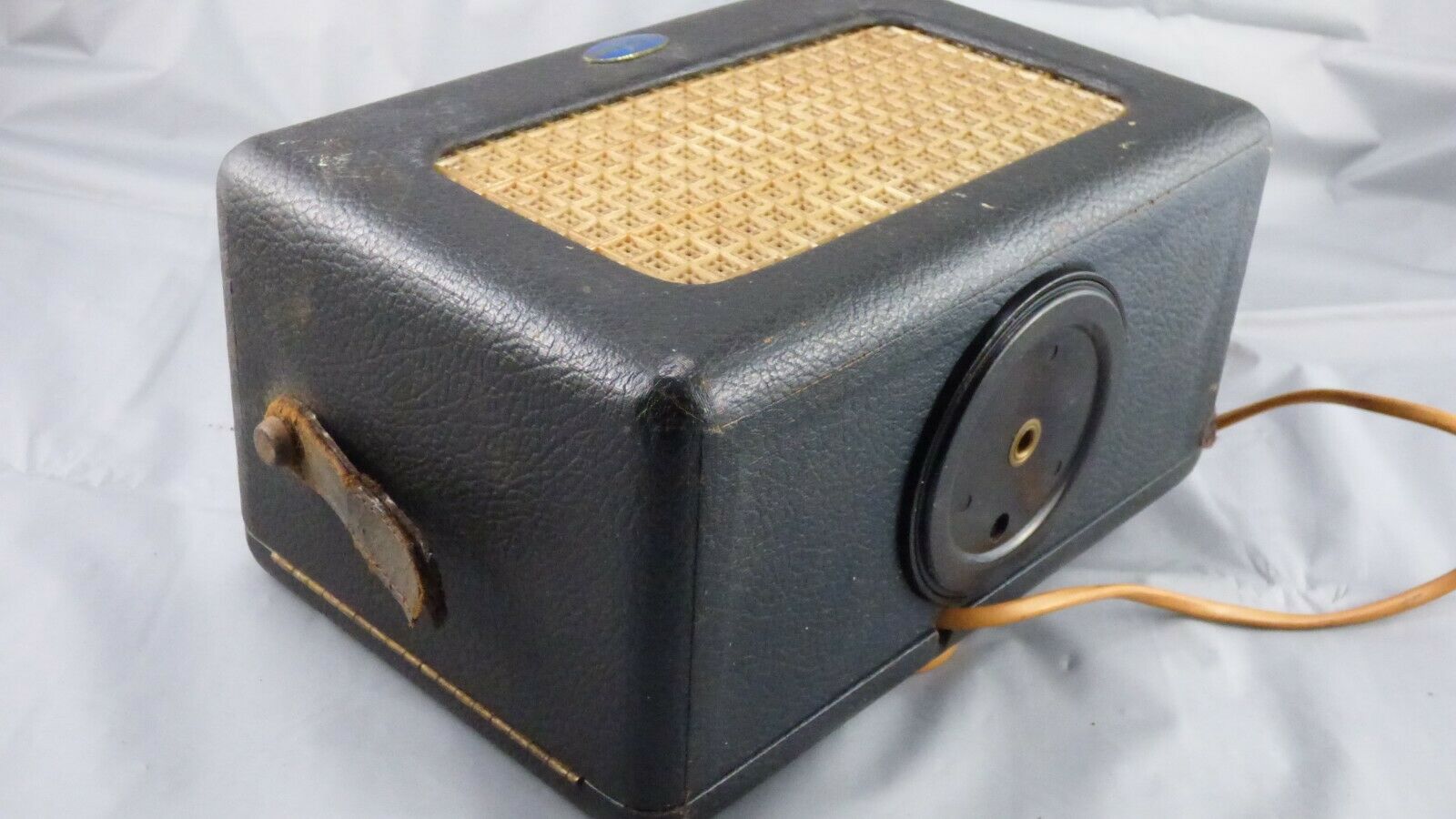
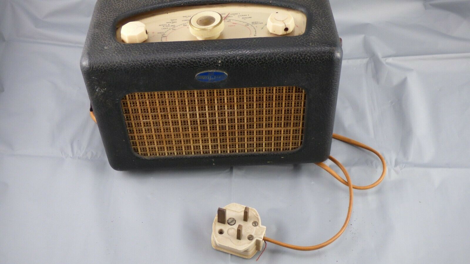
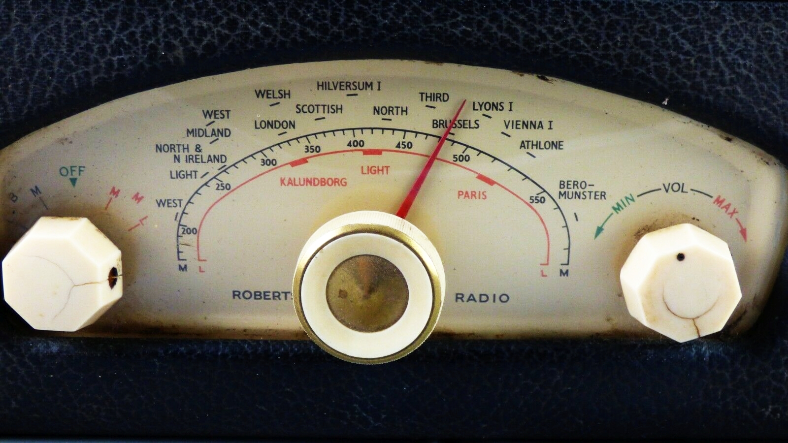
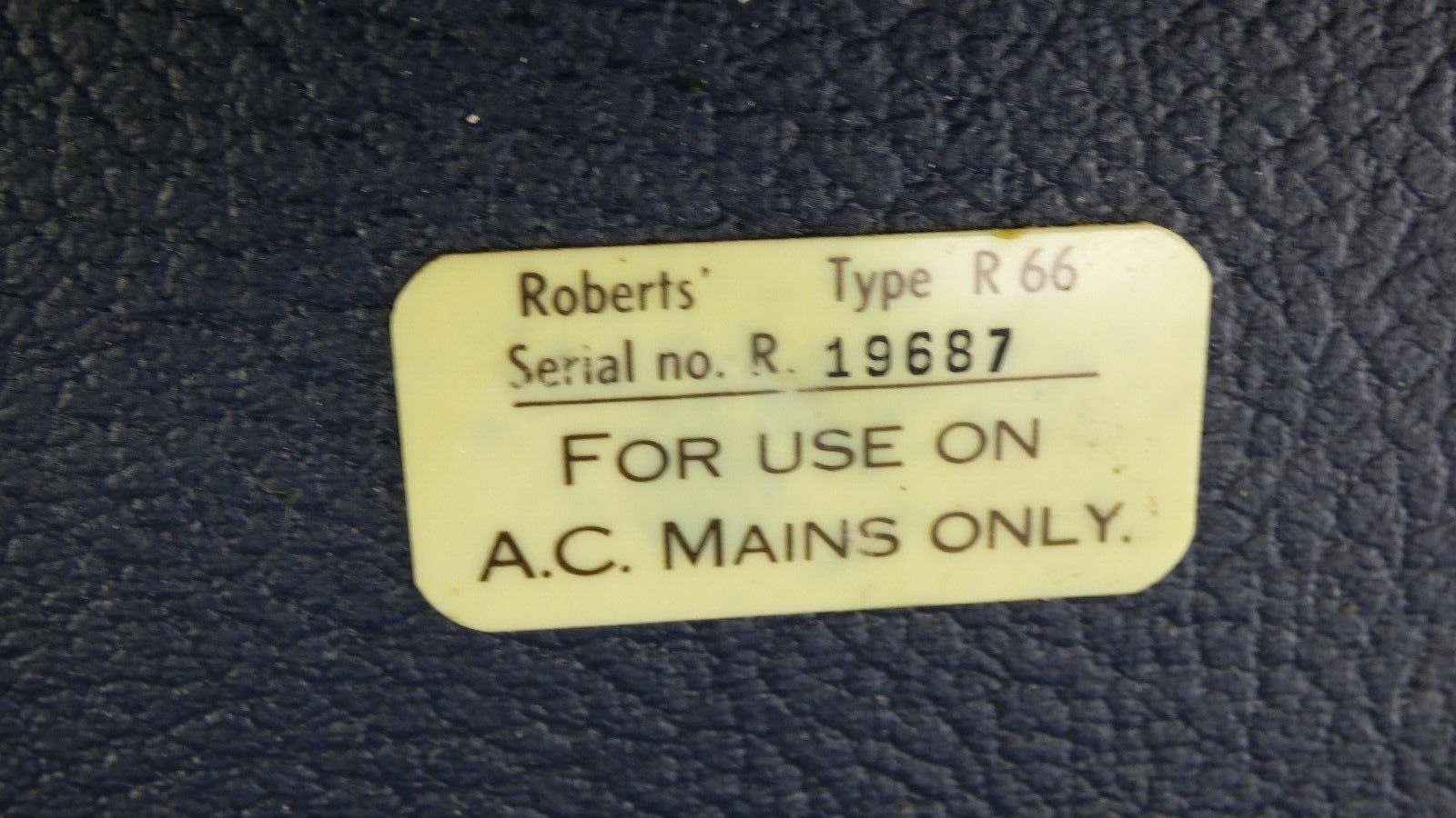
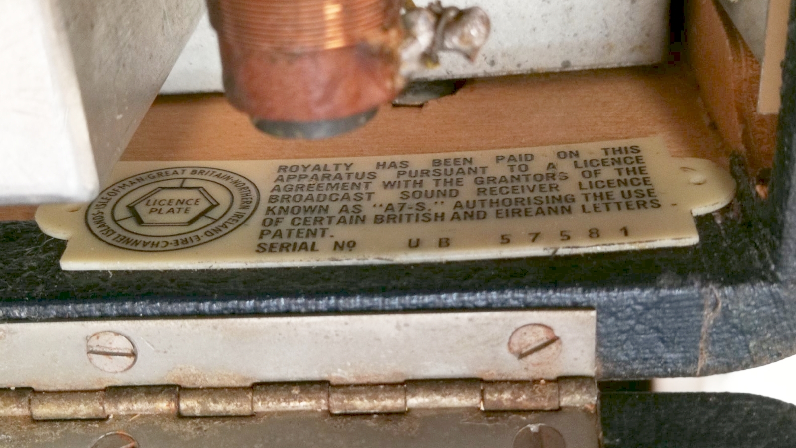
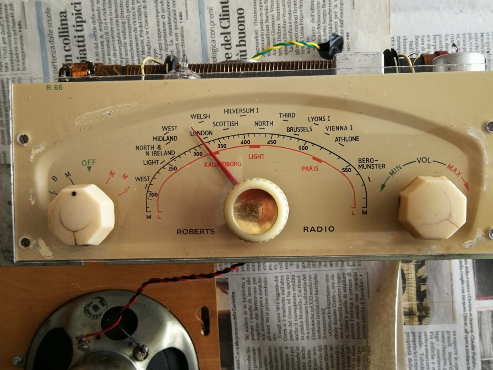
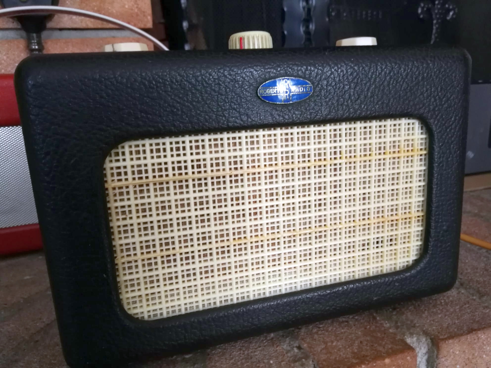
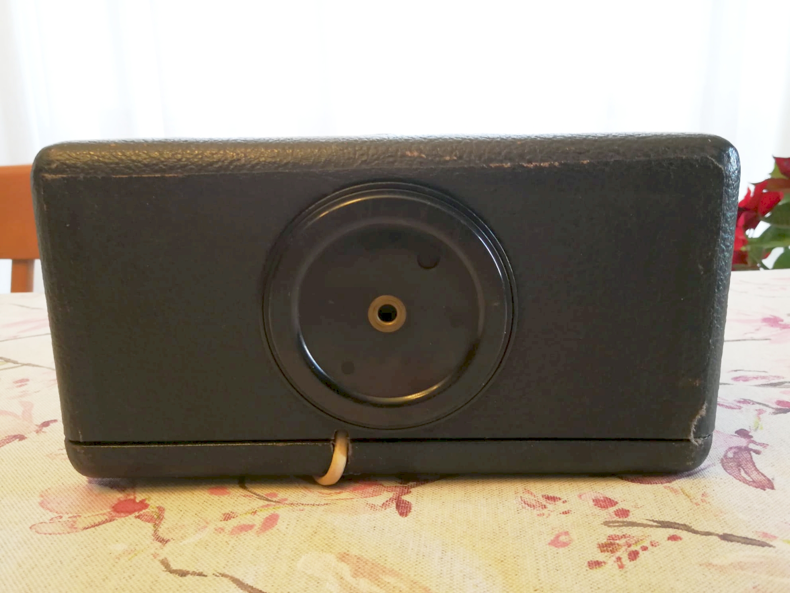
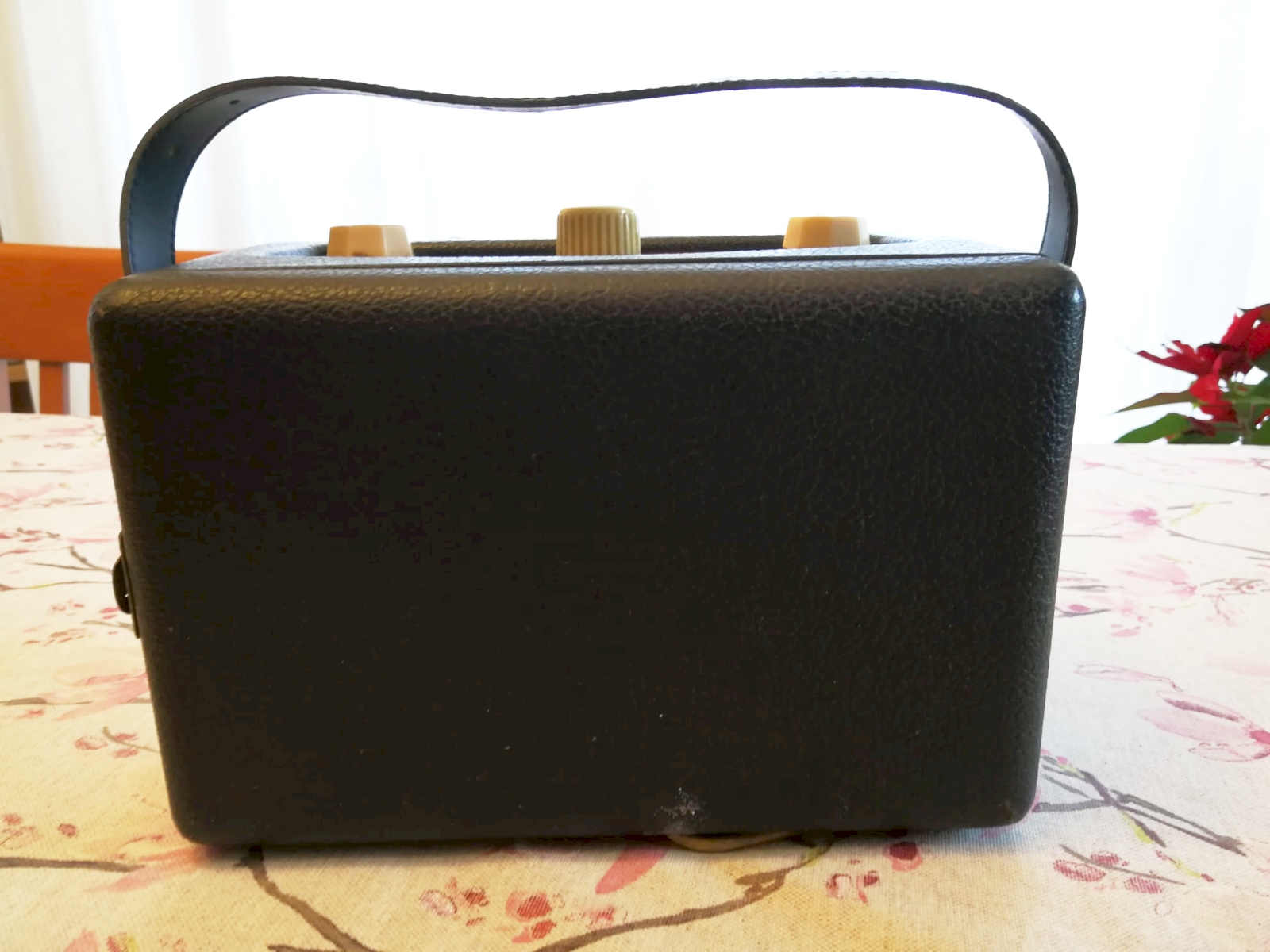
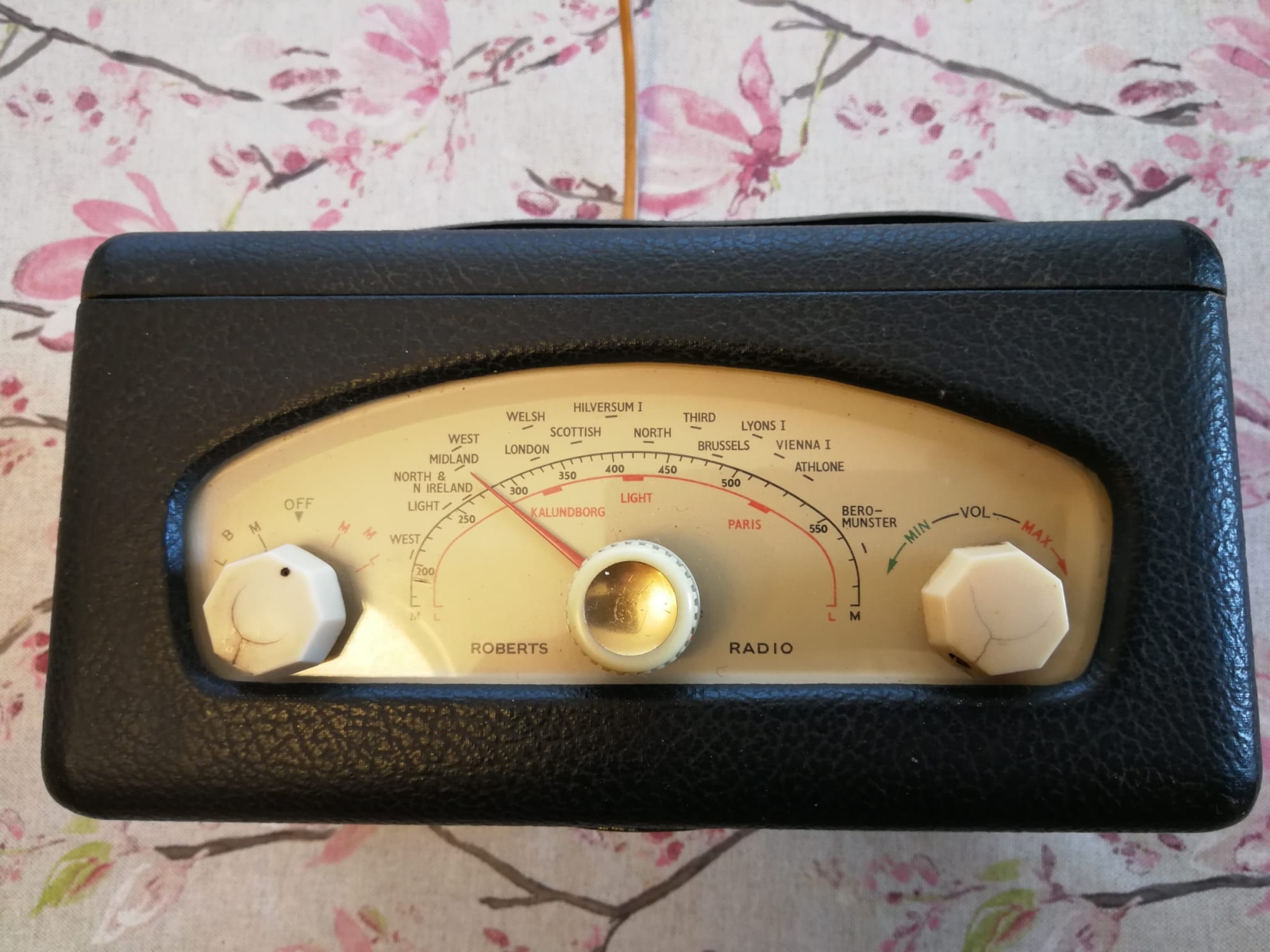
R66 - Great Britain 1956.Roberts Radio Co. Ltd. marketed this portable tube receiver starting in 1956. Like the previous R55 model, the 66 could also receive Medium Wave and Long Wave, respectively from 182 to 180 m and from 900 to 2000 metres. Like the previous one, the circuit was a superheterodyne with medium frequency at 470 KHz and which used the same four Mullard miniature type valves: DK96, DF96, DAF96 and DL96. The power could be supplied by two dry batteries: a 1.5 V AD4 type for the filaments and a 90 V B126 type for the anode voltage, or it could be connected to the mains because the R66 had the appropriate power supply. The selling price in 1956 was £13, 19S and 9d including batteries but excluding tax. The antenna used had coils wound around a long ferroxcube core and was directional, therefore by rotating the radio it was possible to seek the best position for signal reception. Like the R55, the R66 was also equipped with a double black plastic disc in the lower part of the cabinet which allowed an easy rotation. Two plastic labels were glued inside the cabinet: one on the rear cover bore the serial number which in the example that arrived to me was 19687, the other was glued inside the right side of the cabinet seen from behind and it certified that Roberts had paid royalties for the license to receive public radio broadcasts. IK3HIA © 2022 |
|||||
|
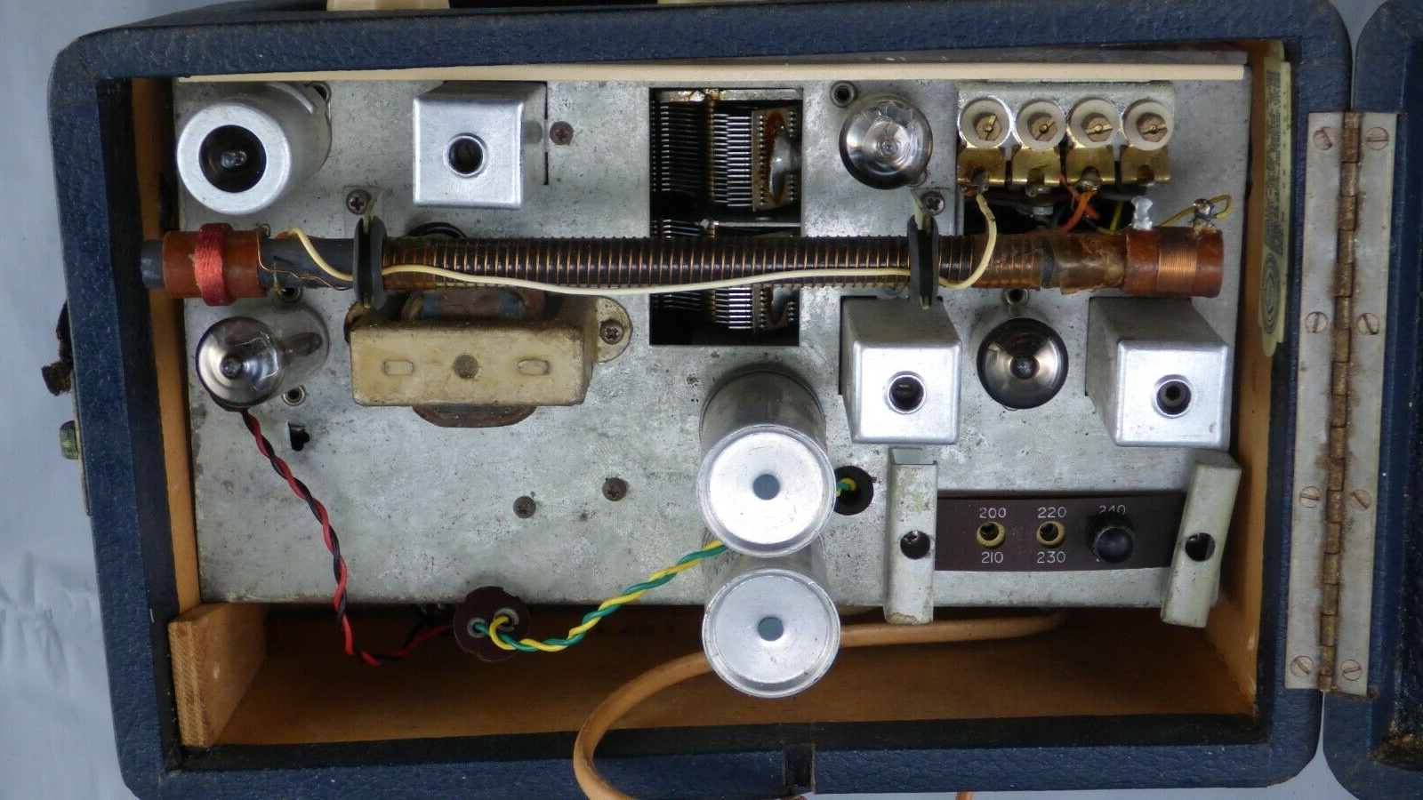
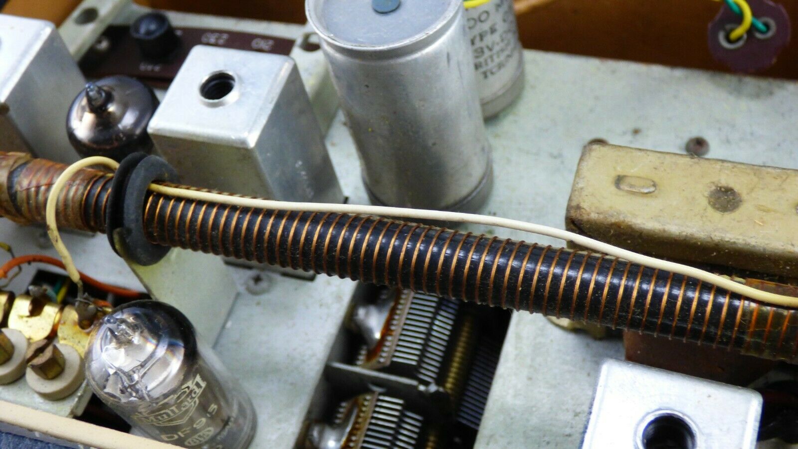
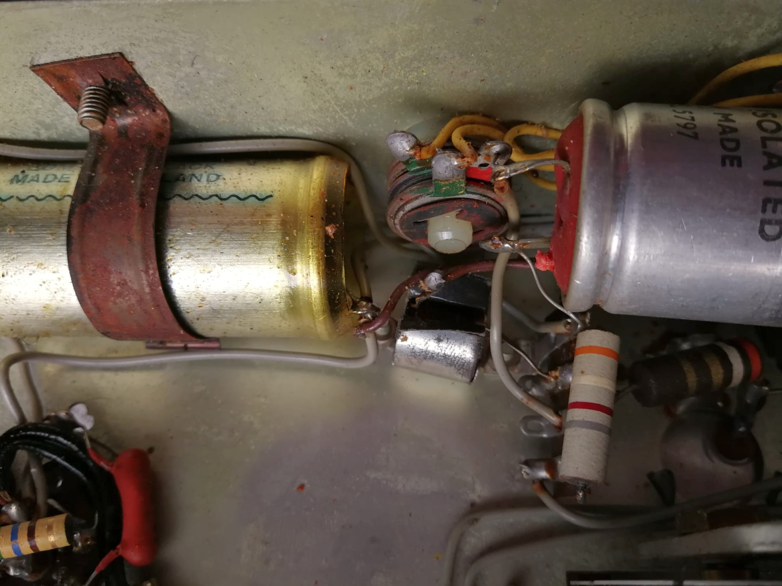
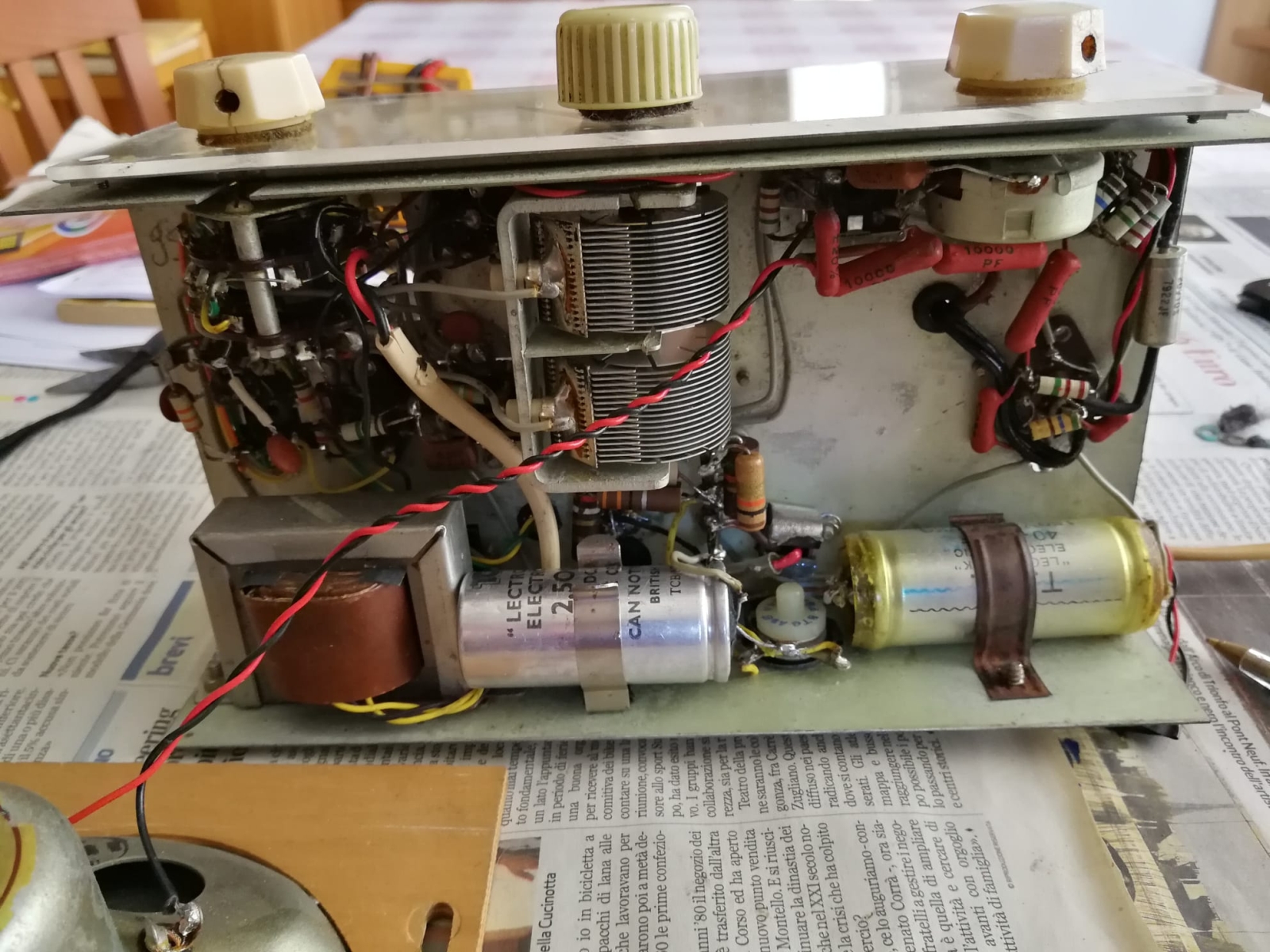
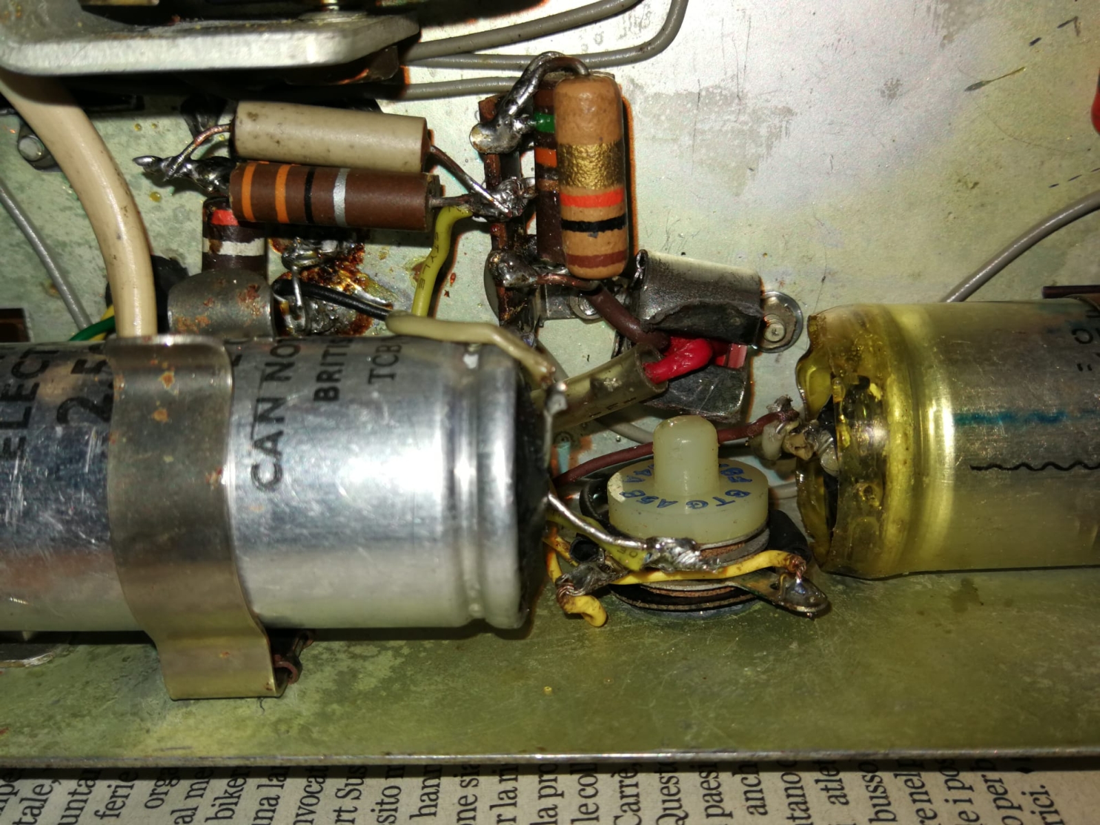
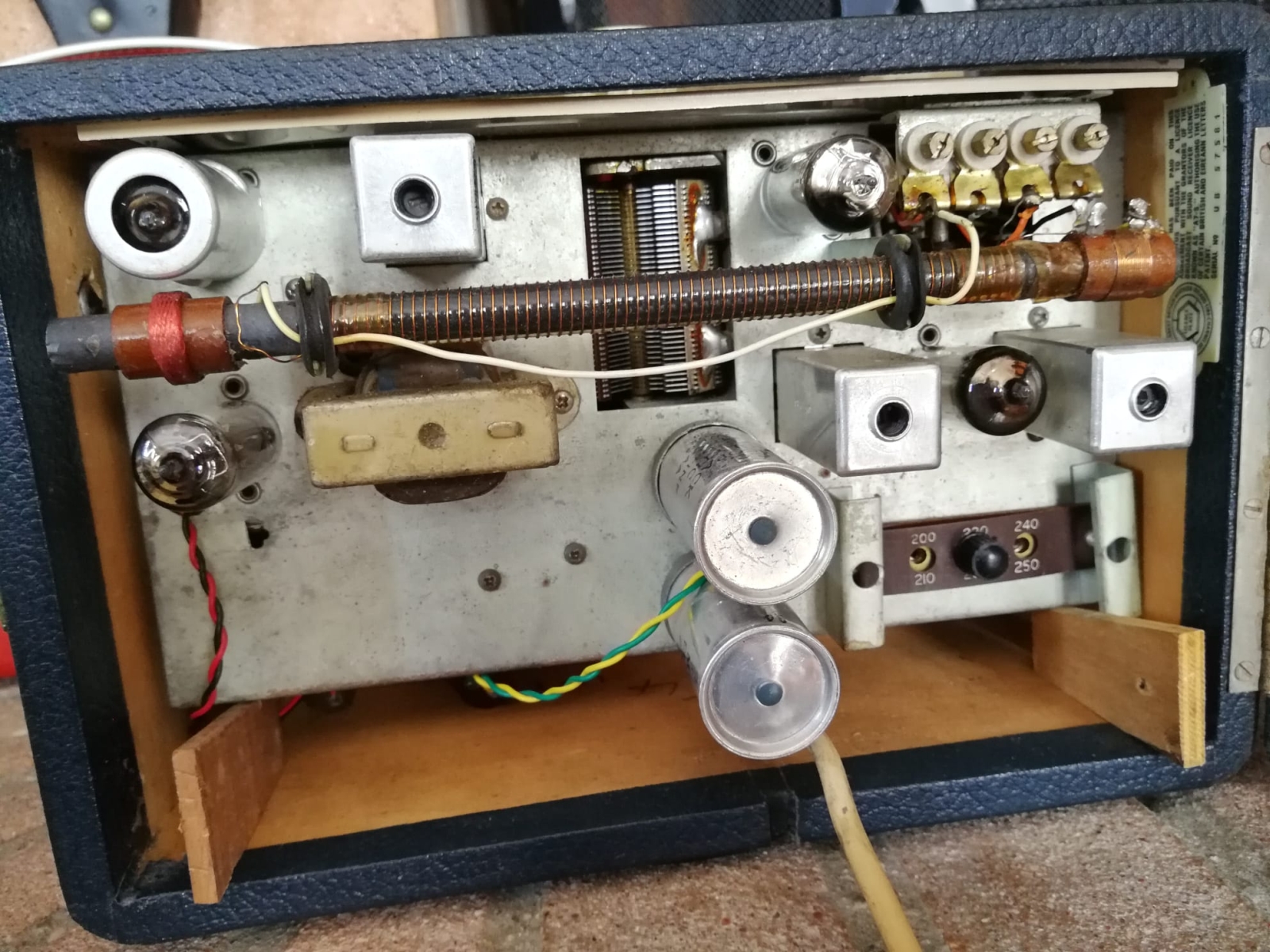
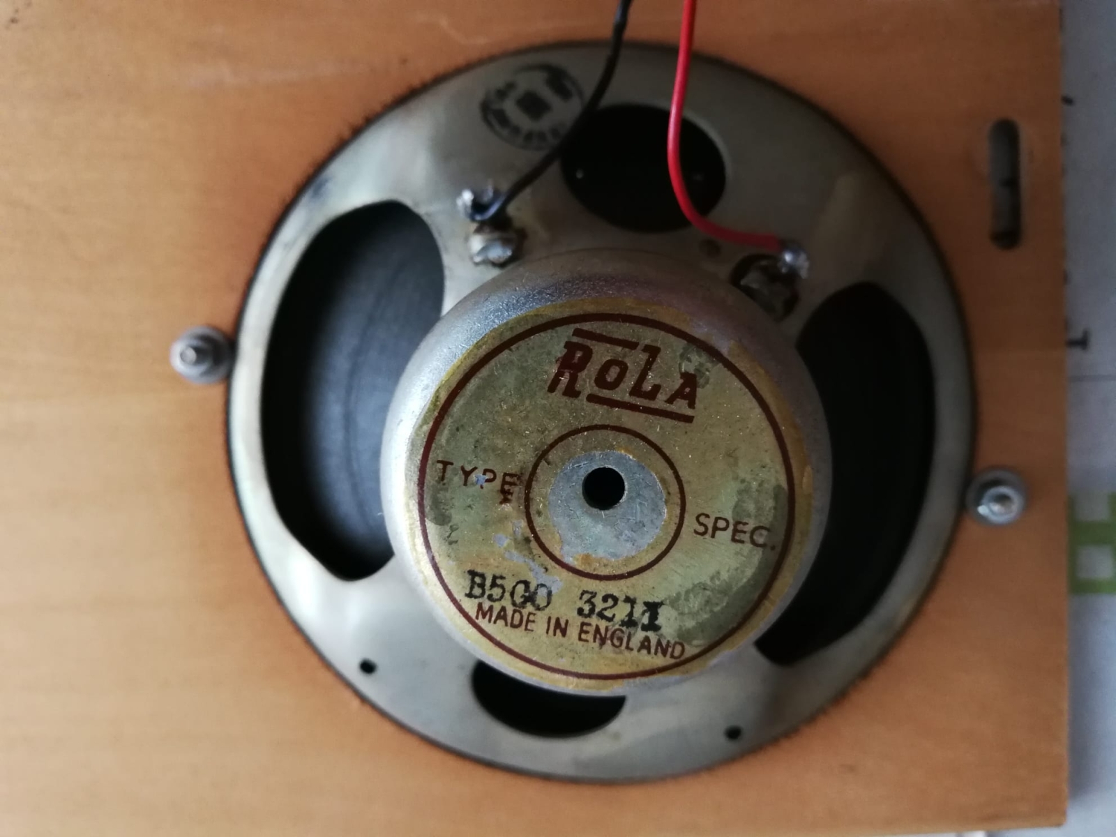
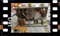
Images taken during the restoration
|
|||||
 |
 |
 |
 |
||
 |
 |
 |
 |
||
|
Back to the top of the page
|
|||||
|
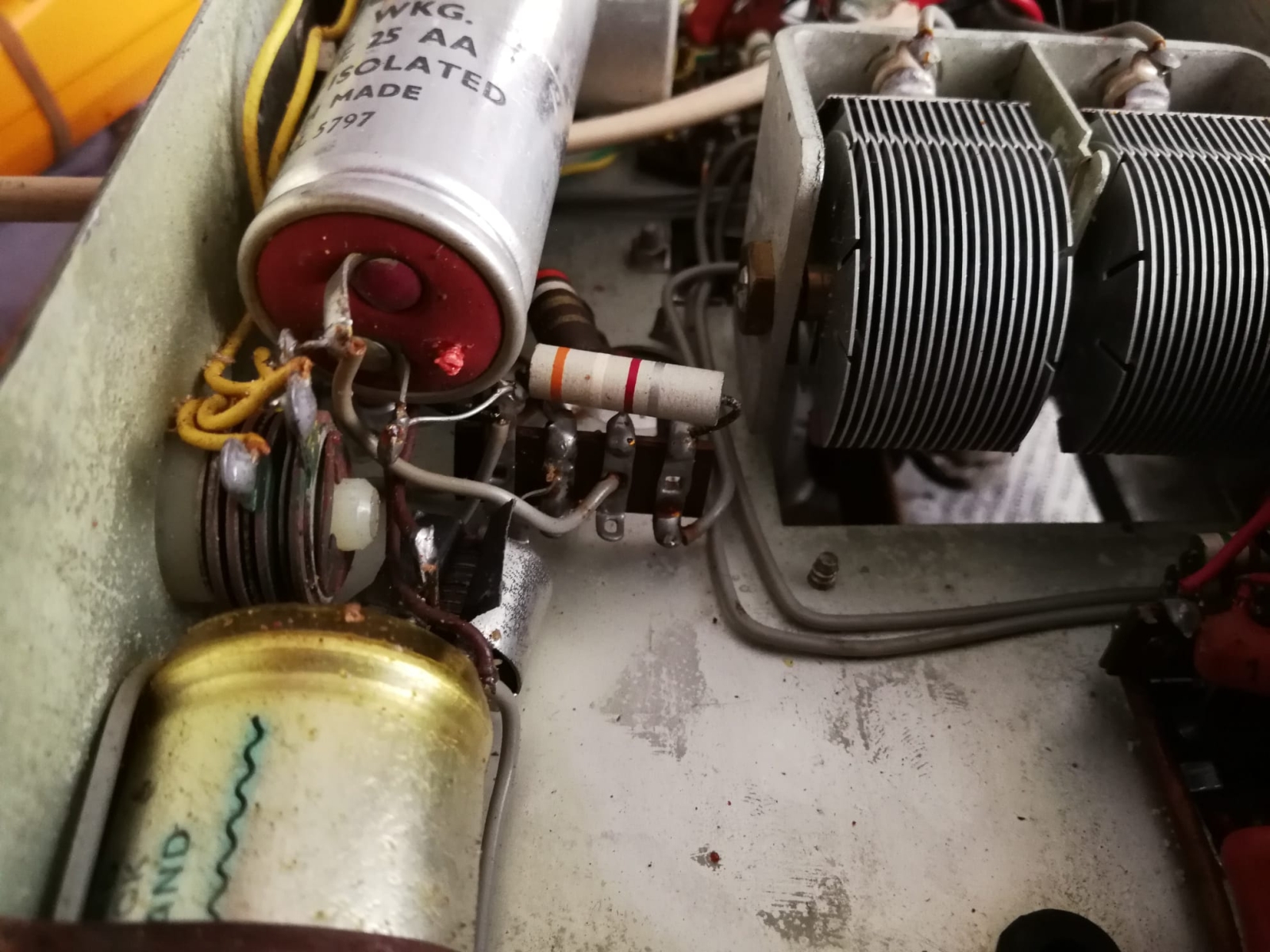
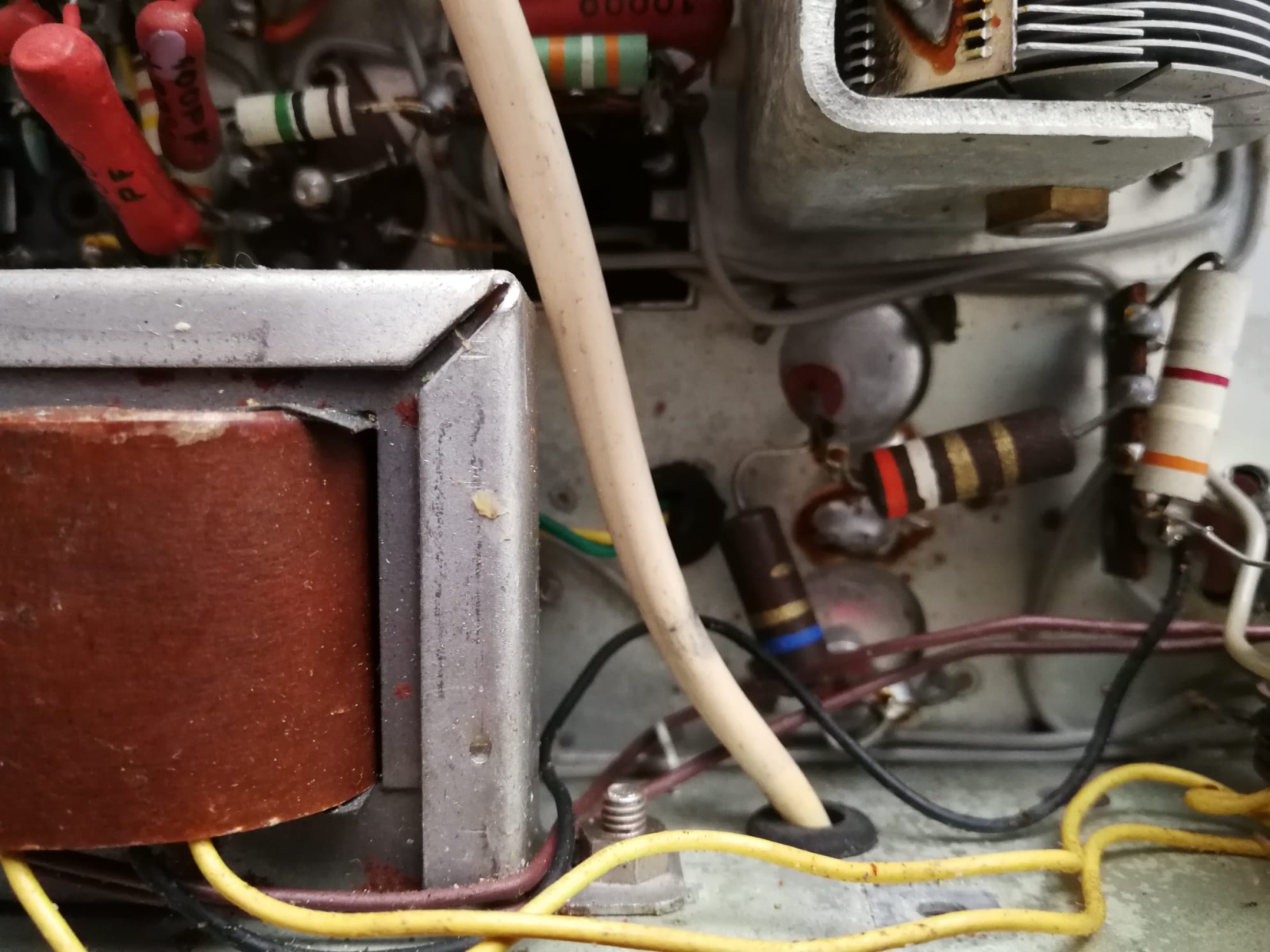
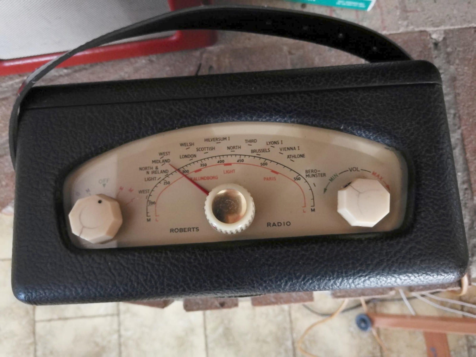
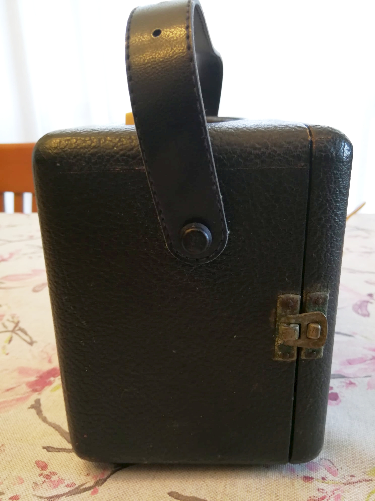
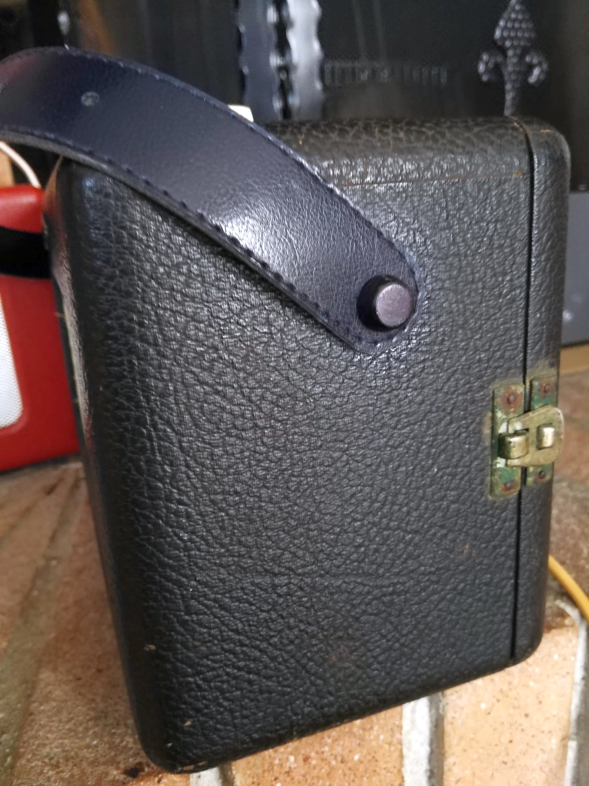
Restoration The R66 in my possession arrived to me not working, the tuning knob was not original and the transport belt was broken. I started by checking the four valve filaments with the tester and how they work with my TV-7U tube tester. All Mullard tubes came out with good filament and still working. Risking a bit I connected the radio to a transformer which supplies 110Vac rather than the 220V required by the R66. With the tester I measured the AC voltage output from the transformer high voltage secondary and found about 60 Vac, after the MR1 diode instead there were only a few volts DC. This was also the case for the the filaments low voltage: the AC was present but the DC did not pass through MR2. The obvious conclusion was that given the age (more than sixty years) the two metallic rectifier elements had become highly resistive. In addition, the electrolytic capacitors under the chassis looked suspicious, with what appeared to be leaking electrolyte. I rolled up my sleeves and started replacing the electrolytic capacitors. In order not to "ruin" the vintage look of the device, with a little good will I managed to remove the old content and insert new components of adequate capacity and higher insulation voltage into the original casings. Since the new elements were much smaller, it was not a problem to insert them, get the leads out of plastic washers cut with scissors and fix everything with epoxy glue. As for the copper oxide rectifier diodes, the solution to the problem was more laborious. Instinct suggested replacing the old diodes with modern silicon elements. However, I realized that the internal resistance of the silicon diodes would be much lower than that of the old metal rectifiers, so connecting them to the pre-existing circuit there was the risk of obtaining too high voltages and causing the destruction of the valves, especially as regards the filaments. I proceeded step by step, the anode voltage had to be 90 V so if I replaced the old MR1 rectifier with a modern 1N4007 diode, the R14 resistor (formerly 3.9 kOhm) had to have a higher value. I did various tests starting from 20 kOhm downwards and in the end I found that with a 6.35 kOhm R14, downstream I obtained 90 Vdc. To achieve the unusual resistive value I connected in series-parallel a pair of old 1W resistors found in my drawer of wonders until the desired value was reached. I soldered the new 1N4007 diode in a "hidden" position behind the rheophores of the old MR1 from which I had previously removed the copper disks. The absorption of the filaments of the 4 valves at 1.4 V was 125 mA and in this case to rectify the filament voltage inside the previously emptied casing of MR2 I was able to conveniently insert 2 x 1N4004 diodes and after some tests I established that the resistance R15 had to be 4.5 Ohm and R16 13.3 Ohm both at least 2 W. To carry out the work I had removed the chassis from the cabinet, so I also proceeded to remove the dust from the tuning scale, the loudspeaker and the related grille. I used contact cleaner spray on the volume pot and range shifter. At this point I connected the radio to the 220 V electrical socket and I was able to verify the proper functioning of the device by tuning into a Medium Wave station. All I had to do was fix the old radio look. In my magical wonder drawer I tracked down an old knob more "in tune" with the style of the radio, then I thought about how to replace the broken drive belt. A visit to a near weekly fleat market yielded a one inch wide women's dress strap in a dark blue colour, a little wider than the original but similar in color to the imitation leather that covered the cabinet of the R66. Once I got home I cut the new belt to the right size, drilled it and installed it in place of the remaining pieces of the old one, also restoring this lack of the R66. IK3HIA © 2022 |
|||||
|
Images taken after the restoration
|
|||||
 |
 |
 |
 |
||
 Roberts R66 - Gran Bretagna 1956.
La Roberts Radio Co.Ltd. commercializzò questo ricevitore portatile a valvole a partire dal 1956. Come il modello precedente R55, anche la 66 poteva ricevere le Onde Medie e le Onde Lunghe, rispettivamente da 182 a 180 m e da 900 a 2000 metri. Come il precedente il circuito era una supereterodina con Media frequenza a 470 KHz e che utilizzava le stesse quattro valvole tipo miniatura della Mullard: DK96, DF96, DAF96 e DL96. L'alimentazione poteva essere fornita da due batterie a secco: una tipo AD4 da 1,5 V per i filamenti e una tipo B126 da 90 V per la tensione anodica, oppure la R66 poteva essere collegata alla rete elettrica perché disponeva dell'apposito alimentatore in alternata. Il prezzo di vendita nel 1956 era di 13 sterline 19 Scellini e 9 pence comprese le batterie ma le tasse erano escluse. L'antenna utilizzata aveva le bobine avvolte su un lungo nucleo ferroxcube ed era direzionale, pertanto ruotando la radio si poteva cercare la migliore posizione per la ricezione del segnale. Come la R55, anche la R66 nella parte inferiore del mobile era dotata di un doppio disco di plastica nera che permetteva una comoda rotazione. All'interno del mobile erano incollate due etichette di plastica: una sul coperchio posteriore riportava il numero seriale dell'apparecchio che nell'esemplare arrivatomi era la 19687, l'altra invece era incollata all'interno del lato destro del mobile visto da dietro e certificava che la Roberts aveva pagato le royalty per la licenza di ricezione delle trasmissioni radio pubbliche. IK3HIA © 2022 |
|||||
|
Back to the top of the page
|
|||||
 |
 |
 |
 |
||
|
Restauro L'esemplare di R66 in mio possesso mi è arrivato non funzionante, la manopola della sintonia non era originale e la cinghia di trasporto era rotta. Ho iniziato controllando i filamenti delle quattro valvole con il tester e il loro funzionamento con il provavalvole TV-7U. Tutti i tubi della Mullard sono risultati con il filamento buono e ancora efficienti. Rischiando un po' ho collegato la radio a un trasformatore che fornisce 110 V alternati anziché i 220 V richiesti dall'R66. Con il tester ho misurato l'uscita della tensione alternata dal secondario del trasformatore e ho trovato 60 Vac, dopo il diodo MR1 invece c'erano solo pochi volt continui. Così è stato anche per la tensione dei filamenti: l'alternata era presente ma da MR2 non passava la continua. L'ovvia conclusione è stata che vista l'età (più di sessant'anni) i due elementi raddrizzatori metallici erano diventati fortemente resistivi. In più i condensatori elettrolitici posti sotto lo chassis avevano un aspetto sospetto, con quelle che sembravano perdite di elettrolita. Mi sono rimboccato le maniche e ho iniziato con il sostituire i condensatori elettrolitici. Per non "rovinare" l'aspetto vintage dell'apparecchio, con un po' di buona volontà sono riuscito ad asportare il vecchio contenuto e inserire negli involucri originali dei componenti nuovi di adeguata capacità e superiore tensione di isolamento. Essendo i nuovi elementi molto più piccoli non è stato un problema inserirli, far uscire i reofori da rondelle di plastica ritagliate con le forbici e fissare il tutto con la colla epossidica. Per quanto riguardava invece i diodi raddrizzatori a ossido di rame la soluzione del problema è stata più laboriosa. L'istinto suggeriva di sostituire i vecchi diodi con dei moderni elementi al silicio. Però mi rendevo conto che la resistenza interna dei diodi al silicio sarebbe stata molto inferiore a quella dei vecchi raddrizzatori metallici, perciò collegandoli al circuito preesistente c'era il rischio di ottenere tensioni troppo alte e provocare la distruzione delle valvole specialmente per quanto riguardava i filamenti. Ho proceduto per gradi, la tensione anodica doveva essere di 90 V quindi se sostituivo il vecchio raddrizzatore MR1 con un moderno diodo 1N4007 la resistenza R14 (ex 3,9 kOhm) doveva avere un valore più alto. Ho fatto varie prove partendo da 20 kOhm in discesa e alla fine ho trovato che con una R14 di 6,35 kOhm, a valle ottenevo 90 Vdc. Per realizzare l'insolito valore resistivo ho collegato in parallelo un paio di vecchie resistenze da 1W trovate nel mio cassetto delle meraviglie fino al raggiungimento del valore desiderato. Il nuovo diodo 1N4007 l'ho saldato in posizione "nascosta" dietro ai reofori del vecchio MR1 al quale avevo asportato preventivamente i dischetti di rame. L'assorbimento dei filamenti delle 4 valvole a 1,4 V era di 125 mA e in tal caso per raddrizzare la tensione di filamento all'interno dell'involucro precedentemente svuotato di MR2 ho potuto comodamente inserire 2 diodi 1N4004 e dopo alcune prove ho ho stabilito che la resistenza R15 doveva essere di 4,5 Ohm e R16 di 13,3 Ohm ambedue da almeno 2 W. Per effettuare il lavoro avevo tolto lo chassis dal mobile, perciò ho provveduto anche a togliere la polvere dalla scala di sintonia, dall'altoparlante e dalla relativa griglia. Ho usato lo spray pulisci contatti sul potenziometro del volume e sul commutatore del cambio gamma. A questo punto ho collegato la radio ai 220 V della presa elettrica e ho potuto verificare il buon funzionamento dell'apparecchio sintonizzando una stazione in Onde Medie. Non mi rimaneva che rimediare all'aspetto della R66. Nel mio magico cassetto delle meraviglie ho rintracciato una vecchia manopola più "in sintonia" con lo stile della radio, poi ho pensato a come sostituire la cinghia di trasporto rotta. Una visita a un vicino mercatino settimanale mi ha fruttato una cinghia da abbigliamento femminile larga 2,5 cm e di colore blu scuro, un pochino più larga dell'originale ma di tinta simile a quello della finta pelle che rivestiva il mobiletto della R66. Una volta ha casa ho tagliato la nuova cinghia nella giusta misura, l'ho forata e installata al posto dei pezzi rimanenti della vecchia, ripristinando anche tale mancanza della R66. IK3HIA © 2022 |
|||||
|
Schematics |
|||||
 |
 |
 |
|
||
|
Back to the top of the page
|
|||||
|
|
|
Return to: IK3HIA page |
|
Return to Roberts Radio page
|