 |
Philips mod. L3X02T/00
- Nederland - 1960 - Restoration - |
 |
 Restoration
 Description
 |
 |
Restauro
 Schemi elettrici Descrizione  |
|
|
Click sulle immagini per
ingrandire
|
|||
 |
 |
 |
 |
 Philips L3X02T - Restoration
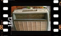
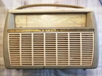
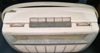
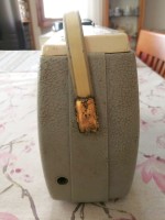
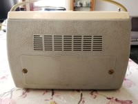
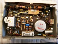
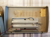
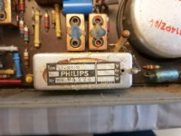
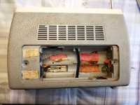
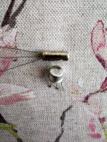
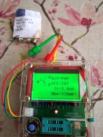
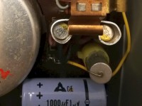
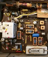
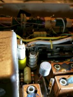
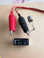
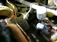
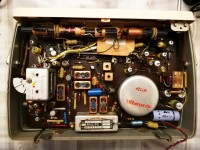
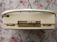
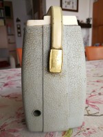
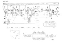
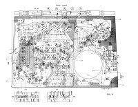
The L32X02T sample I bought was in really bad condition. The radio cabinet was badly damaged, with the gilded parts corroded, the index of the talking scale blocked and the cabinet was so dirty and stained as to imagine that the radio had been forgotten on a shelf in some cellar for years. Once the rear shell was removed, the conditions of the electrical circuit at first glance seemed quite good to me, but a quick check with the Ohmmeter on the power wires immediately dissuaded me from applying voltage: between the plus and minus of the cables connected the printed circuit board to the battery compartment there was a clear short circuit. After having uselessly replaced the 1000 µF 25 VW electrolytic capacitor C57 (at the ends of which I found a clear short circuit), equipped with tweezers to dissipate the heat, I unsoldered the two transistors T7 and T8 of the audio power stage from the printed circuit. Both OC74s had shorted collector with the emitter. Once the culprits had been removed and the resistance between the positive and negative poles of the power supply had been measured again with the tester, the short circuit had disappeared, so in order to proceed with the repair it was necessary to replace the two power transistors. Finding a selected pair of OC74s on the market today is almost impossible, and even single specimens are offered at disproportionate prices. The radio wasn't worth that expense, maybe everything else was burnt too so to attempt the restoration it was absolutely necessary to find a pair of low-cost replacements. After having carefully examined the contents of my magic drawer, I found a bag containing a dozen of old PNP germanium transistors from marked Texas 6843. They were transistors disassembled from old computer boards of which I have never found on the internet and in the various manuals the characteristics, but the TO-5 type case and the use for which they were designed suggested that they could handle a fair amount of collector current. Why not try to burning a couple? Using my Transistor Tester I selected a pair of transistors with similar HFE (gain), then keeping the rheophores cool with the self-closing tweezers I soldered the two Texas on the Philips printed circuit instead of the OC74s. An ohmmeter check at the supply voltage input now gave me a resistance of 283 ohms, which was no longer a short. With a little fear I first applied six and then nine Volts to the circuit without causing any explosions or strange smoke. A crackling sound came from the loudspeaker when switched on, otherwise the radio remained silent even when changing the reception range, the two 6843s on the other hand did not heat up. Calling up my Heathkit SG8 generator I applied a 400Hz audio signal on the T6 base (OC75) and the tone came out very loud from the speaker. By moving the probe to the input of the low frequency stage I had to adjust the volume potentiometer because the sound was really deafening. One thing was therefore certain, the two old Texas PNP transistors did their job as good replacements. Adjusted the generator on 460 kHz and switched the radio to Medium Waves I applied the high frequency signal on the base of the T4 (OC170). No tone came out of the loudspeaker: therefore the problem was in the Intermediate Frequency stage. The typical problem of those old High Frequency transistors of the early sixties immediately came to my mind: the AC11x and OC17x series suffered over time from the phenomenon of the growth of very thin metal whiskers inside their casing, the "tin whiskers". These few micron-thick "whiskers" shorted one or more internal rheophores with the metal casing, making the transistor inert (more information at this link). There were two solutions: apply a voltage discharge of about thirty Volts to the rheophores of the transistor to "burn" the metal whiskers in the "sick" transistor or replace it with an equivalent not afflicted by the same problem. With the replacement of the transistors of the final power stage, the old Philips had already undergone an unorthodox transplant, so I decided to try the first solution. After unsoldering from the circuit board all the transistors of the high frequency part (T1, T2, T3, T4) I prepared the necessary equipments: a 220 MF 63 VW electrolytic capacitor and my multivoltage power supply. After having "charged" the capacitor with 36 Volts, I shorted the base, emitter and collector of the first OC171, I connected these leads to the negative capacitor pole and I "touched" the S (screen) rheophore of the transistor with the positive causing an invisible discharge. I repeated the operation with the other OC171 and with the two OC170s, then I re-soldered all the "fried" OC17x in their place on the PCB of the L32X02T. Selected the FM range I turned on the radio and to my extreme surprise and great satisfaction some music came out of the loudspeaker: the strange elettroshock "cure" had worked successfully! In the following days I replaced some electrolytic capacitors, I calibrated the Intermediate Frequency transformers, cleaned the contacts of the push-button panel and the volume potentiometer with the deoxidizing spray and fixed the the dial scale cord. Then I wasted a lot of time cleaning the cabinet as best as possible with a detergent and "going over" the golden parts with a felt-tip gold-colored pen. Since the two Texas TO-5 transistors had a bigger case than the OC74s it was not possible to insert them in the original heat sinks. The two 6843s were actually barely warm after an hour of pretty loud music, but just to be safe I cut out and bent a small strip of aluminum foil In order to make a kind of heat sink with the appropriate dimensions. After being cleaned and put back in working order, the Philips L3X02T could rightfully become part of my radio collection. © IK3HIA 2023. |
|||
 |
 |
 |
 |
 |
 |
 |
 |
|
Back to the top of the page >>
|
|||
 Philips L3X02T - Restauro
 L'esemplare di L32X02T che ho acquistato era davvero in pessime condizioni. Il mobiletto della radio era parecchio rovinato, con le parti dorate corrose, l'indice della scala parlante bloccato e il mobile era talmente sporco e macchiato da immaginare che la radio fosse rimasta dimenticata per anni su uno scaffale in qualche cantina. Una volta tolto il guscio posteriore, le condizioni del circuito elettrico a prima vista mi sono sembrate abbastanza buone, ma un rapido controllo con l'Ohmmetro sui fili di alimentazione mi ha subito dissuaso dall'applicare tensione: tra il più e il meno dei cavetti che collegavano il circuito stampato al vano porta batterie c'era un netto cortocircuito. Dopo aver inutilmente sostituito il condensatore elettrolitico C57 da 1000 µF 25 VL (ai capi del quale trovavo un netto cortocircuito), munito delle pinzette per dissipare il calore ho dissaldato dal circuito stampato i due transistor T7 e T8 dello stadio di potenza audio. Ambedue gli OC74 avevano collettore ed emitter in cortocircuito. Una volta tolti i colpevoli e misurato ancora con il tester la resistenza tra il polo positivo e il negativo dell'alimentazione il cortocircuito era scomparso, perciò per poter procedere con la riparazione bisognava sostituire i due transistor di potenza. Trovare in commercio una coppia selezionata di OC74 oggi è pressoché impossibile, e anche gli esemplari singoli vengono proposti a prezzi spropositati. La radio non valeva tale spesa, magari era bruciato anche tutto il resto perciò per tentare il restauro bisognava assolutamente trovare un paio di sostituti a basso costo. Dopo aver esaminato attentamente il contenuto del mio cassetto magico, ho trovato una bustina con dentro una decina di vecchi transistor PNP al germanio della Texas con la sigla 6843. Erano dei transistor smontati da vecchie schede di computer dei quali su internet e nei vari manuali non ho mai trovato le caratteristiche, ma l'involucro tipo TO-5 e l'utilizzo per cui erano stati progettati suggeriva che potessero sopportare una discreta corrente di collettore. Perché non provare a bruciarne un paio? Utilizzando il mio Transistor Tester ho selezionato un paio di transistor con HFE (guadagno) simile, poi tenendo raffreddati i loro reofori con la pinzetta autochiudente ho saldato i due Texas sul circuito stampato della Philips al posto degli OC74. Un controllo con l'Ohmmetro tra i capi di C57 adesso mi dava una resistenza di 283 Ohm, la quale non era più un cortocircuito. Con un po' di timore ho applicato dapprima sei e poi nove Volt al circuito senza provocare scoppi o fumate strane. Dall'altoparlante usciva un crepitio all'atto dell'accensione, per il resto la radio rimaneva muta anche cambiando la gamma di ricezione, i due 6843 in compenso non scaldavano. Chiamato in causa il mio generatore Heathkit SG8 ho applicato un segnale audio di 400 Hz sulla base del T6 (OC75) e il tono è uscito molto forte dall'altoparlante. Spostando la sonda all'ingresso dello stadio di Bassa frequenza ho dovuto regolare il potenziometro del volume tanto il tono era assordante. Una cosa era pertanto certa, i due vecchi transistor PNP della Texas facevano il loro dovere da bravi sostituti. Regolato il generatore sui 460 kHz e commutato la radio su Onde Medie ho applicato il segnale di alta frequenza sulla base del T4 (OC170). Dall'altoparlante non usciva nessun tono: il problema quindi era nello stadio di Frequenza Intermedia. Subito mi è venuto in mente il tipico problema di quei vecchi transistor di Alta Frequenza dei primi anni sessanta: le serie AC11x e la serie OC17x soffrivano con il tempo del fenomeno della crescita di sottilissimi baffi metallici all'interno del loro involucro, i "tin whiskers". Questi "baffi" dello spessore di qualche micron cortocircuitavano uno o più reofori interni con l'involucro metallico rendendo il transistor inerte (maggiori informazioni in questo link). Le soluzioni erano due: applicare una scarica di tensione di una trentina di Volt ai reofori del transistor per "bruciare" i baffi metallici nel transistor "malato" oppure sostituirlo con un equivalente non afflitto dallo stesso problema. Con la sostituzione dei transistor finali la vecchia Philips aveva già subito un trapianto non molto ortodosso, così ho deciso di tentare con la prima soluzione. Dopo aver smontato tutti i transistor della parte Alta frequenza (T1, T2, T3, T4) mi sono preparato l'attrezzatura necessaria: un condensatore elettrolitico da 220 MF 63 VL e il mio alimentatore multitensione. Dopo aver "caricato" il condensatore con 36 Volt, ho cortocircuitato base, emitter e collector del primo OC171, ho collegato tali reofori al negativo del condensatore e ho "toccato" con il positivo il reoforo S (schermo) del transistor provocando un'invisibile scarica. Ho ripetuto l'operazione con l'altro OC171 e con i due OC170, poi ho risaldato tutti gli OC17x "fritti" al loro posto sul circuito stampato della L32X02T. Selezionata la gamma FM ho acceso la radio e con mia estrema sorpresa e con grande soddisfazione è uscita della musica dall'altoparlante: la strana "cura" di elettroshock aveva funzionato con successo! Nei giorni successivi ho sostituito alcuni condensatori elettrolitici, ho eseguito la taratura dei trasformatori di Media Frequenza, ho pulito con lo spray disossidante i contatti della pulsantiera, il potenziometro del volume e ho sistemato il cordino della scala parlante. Poi ho perso parecchio tempo a ripulire al meglio con un detergente il mobiletto e a "ripassare" con un pennarello marcatore le parti dorate. Siccome i due transistor TO-5 della Texas avevano un involucro più grosso degli OC74 non era possibile infilarli nei dissipatori originali. I due 6843 effettivamente erano appena tiepidi dopo un'ora di musica a volume piuttosto alto, ma per sicurezza ho ritagliato e piegato una piccola striscia di alluminio in maniera da realizzare una specie di dissipatore di calore con le dimensioni adatte. Dopo essere stata ripulita e rimessa in grado di funzionare, la Philips L3X02T ha potuto a pieno diritto entrare a far parte della mia collezione di radio. © IK3HIA 2023. |
|||
 |
 |
 |
 |
 |
 |
 |
 |
 |
 |
 |
 |
|
|
|||
|
Back to the top of the page >>
|
|||
|
|
Return to: IK3HIA home page |
|
Return to: Transistor Radio |
|
Go to: Transistor diagrams |