 |
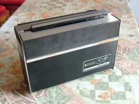
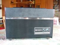
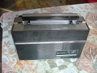
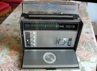
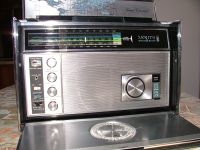
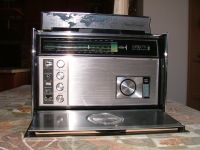
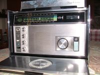
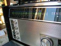
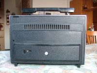
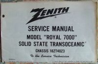
Zenith Transoceanic mod. Royal 7000 U.S.A. - 1969 |
|
|
|
Italiano |
||
|
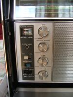
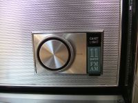
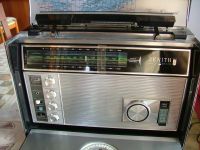
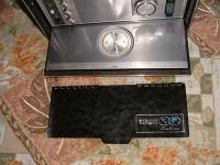
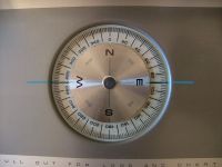
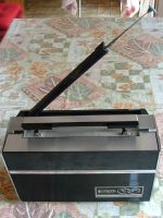
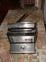
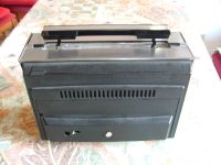
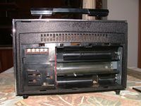
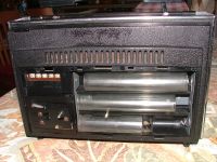
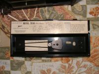
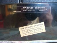
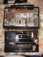
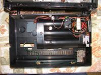
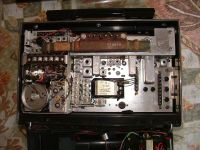
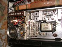
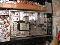
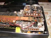
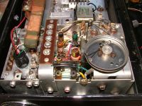
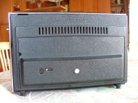
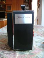
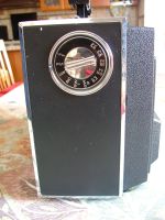
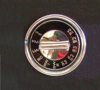
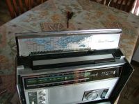
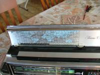
The Royal 7000 was the penultimate Zenith Transoceanic model, but was the last one built in America. The subsequent models (R-7000, -1, -2) while retaining the Zenith brand were built in Taiwan. The 7000 was a portable solid-state receiver that allowed reception on eleven frequency bands: FM with AFC (Automatic Frequency Control), Long Wave, Medium Wave, VHF weather band, and seven Short Wave bands. The special VHF weather band received weather reports on the quartz-controlled frequency of 162.55 MHz. Frequency indication was always analog with the pointer moving on various scales arranged around a rotating drum that moved coaxially with the band change switch. The radio was equipped with a telescopic antenna for FM, VHF and Short Wave, and an internal ferrite antenna for Medium Wave and Long Wave. For Short Waves, the possibility of connecting an external wire antenna via special terminals was maintained. A substantial difference compared to previous models, the 7000 was equipped with a BFO (Beat Frequency Oscillator), a variable oscillator that allowed listening to SSB (Single Side Band) and CW (Morse) signals in all Short Wave bands, an accessory that was essential for listening to radio amateurs who transmitted (and still transmit today) on their assigned frequencies. The circuit of the 7000 was of the single conversion superheterodyne type and used 18 silicon transistors (here is the list), and the Intermediate Frequencies were: 10.7 MHz for FM and 455 KHz for AM/CW/SSB. The radio could be powered by batteries (9 x 1.5V type D or LR20) or via the mains (120 or 220 Vac) using the built-in power supply. On the front panel there were five knobs: BFO, Manual Gain Control, Tone, volume switch and the large tuning knob. Three other switches were used to select: FM-AFC, Bandwidth and reading the tuning indicator instrument. Above the switches in fact there was a milliammeter that indicated the signal being received or the battery charge status. To the right of the tuning knob there was a semi-fixed lamp useful for reading the frequency booklet that was inserted in the pocket of the front cover. The audio stage output power was 500mW max and the loudspeaker impedance was 22 ohms. Dimensions were: 13.2 x 8.3 x 5.6 inch, and weight 13 lb 3.5 oz without batteries. With this model the glorious series of Transoceanic receivers designed and built in the United States ended. Foreign competition, especially from the Japanese Sony and the German Grundig, had gained the upper hand both in terms of the use of new digital components for frequency display and in terms of the performance of large continuous coverage receivers ranging from Long Waves to VHF. © IK3HIA 2007. |
|||
|
|
|||
 |
 |
 |
 |
 |
 |
 |
 |
 |
 |
 |
 |
 |
 |
 |
 |
 |
 |
 |
 |
|
More images below |
|||
|
La Royal 7000 fu il penultimo modello di Zenith Transoceanic, e fu l'ultimo costruito in America. I successivi modelli (R-7000, -1, -2) pur conservando il marchio Zenith vennero costruiti in Taiwan. La 7000 era un ricevitore portatile a stato solido che permetteva la ricezione su undici bande di frequenza: FM con AFC (Automatic Frequency Control), Onde Lunghe, Onde Medie, banda meteorologica VHF, e sette bande di Onde Corte. La speciale banda metereologica VHF riceveva i bollettini meteo sulla frequenza controllata al quarzo di 162.55 MHz. L'indicazione della frequenza avveniva sempre in modo analogico con l'indice che si spostava su varie scale disposte attorno a un tamburo rotante che si muoveva coassialmente al commutatore cambio gamma. La radio era dotata di un'antenna telescopica per la FM, la VHF e le Onde Corte, e di un'antenna in ferrite interna per le Onde Medie e Lunghe. Per le Onde Corte era stata mantenuta la possibilità di collegare tramite appositi morsetti un'antenne filare esterna. Sostanziale differenza rispetto ai modelli precedenti, la 7000 era dotata di BFO (Beat Frequency Oscillator), un oscillatore variabile che permetteva l'ascolto della SSB (Single Side Band) e dei segnali CW (Morse) in tutte le bande delle Onde Corte, accessorio che era indispensabile per ascoltare i radioamatori che trasmettevano (e che trasmettono tutt'oggi) sulle frequenze loro assegnate. Il circuito della 7000 era del tipo supereterodina a singola conversione e utilizzava 18 transistor al silicio (qui c'è la lista), e le Frequenze Intermedie erano: 10,7 MHz per la FM e 455 KHz for AM/CW/SSB. La radio poteva essere alimentata a batterie (9 x 1,5V tipo D o LR20) oppure tramite la rete elettrica (120 o 220 Vca) utilizzando l'alimentatore entrocontenuto. Sul pannello frontale erano collocate cinque manopole: BFO, Controllo Manuale del Guadagno, Tono, interruttore-volume e la grossa manopola della sintonia. Altri tre commutatori servivano per selezionare: FM-AFC, Larghezza di Banda e lettura strumento indicatore di sintonia. Sopra i commutatori infatti era collocato un milliamperometro che indicava il segnale in ricezione oppure lo stato di carica delle batterie. Alla destra della manopola di sintonia era sistemata una lampada semifissa utile per leggere il libretto delle frequenze che era inserito nella tasca del coperchio anteriore. La potenza d'uscita dello stadio audio era di 500 mW max e l'impedenza dell'altoparlante era di 22 Ohm. Le dimensioni erano: 33,5 x 21,2 x 14,2 cm e il peso era di 6 kg senza le batterie. Con questo modello si concludeva la gloriosa serie dei ricevitori Transoceanici progettati e costruiti negli Stati Uniti. La concorrenza straniera, specialmente della giapponese Sony e della tedesca Grundig, aveva preso il sopravvento sia per quanto riguardava l'utilizzo della nuova componentistica digitale per la visualizzazione delle frequenze sia per le prestazioni dei grossi ricevitori a copertura continua che spaziavano dalle Onde Lunghe alle VHF. © IK3HIA 2007. |
|||
|
|
|||
 |
 |
 |
 |
 |
 |
 |
 |
 |
 |
 |
 |
 |
 |
 |
 |
 |
 |
|
 |
| Back to: |
|
IK3HIA home page |
|
Zenith Radio page |
|
Transistor Radio page |
|
Transistor diagrams |