 |
Zenith Long Distance - Universal 6G001YXZ1 - Chassis 6C40Z1 - U.S.A. 1947 |
 |
|
|
Italiano
Restauro |
||
|
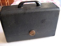
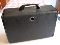
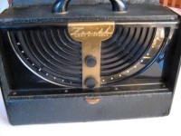
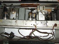
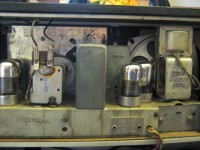
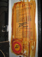
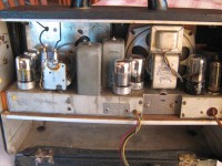
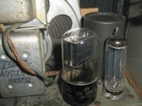
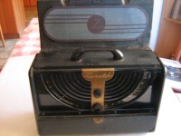
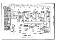
The Zenith 6G001 was a portable tube receiver designed to receive the Medium Wave range with good sensitivity. The radio used a superheterodyne circuit with six electron tubes: 1LN5, 1LA6, 1LN5, 1LH4, 3Q5GT and 117Z3. The antenna was built in and was the typical Zenith frame antenna called "Wavemagnet" which was also used in the Transoceanic models. The conversion frequency (ZF/IF) was at 455 kHz. The cabinet was made of wood covered with a black imitation leather-like film and in terms of structure and circuitry the radio was a reduced version of the contemporary Zenith Transoceanic 8G005TZ1Y model from which it obviously differed in having only one reception band. Once the front panel was opened and lifted by rotating it on the special hinges, the part containing the loop antenna remained positioned vertically above the radio. Below, in the middle of the dial scale, there were two knobs, that of the volume potentiometer with the on and off switch, and the other which, by means of a gear reduction, rotated the variable tuning capacitor. The radio was portable, so it had to be powered by a battery. The battery had to supply two voltages: 9V for the series filaments of the tubes and 90V for the anodic. The battery was the Zenith Z-985 or the RCA VS047 or another equivalent. The battery was placed under the chassis and connected to the radio via a special four-contact connector. Alternatively, the 6G001 could be powered by the 110-120 Vac mains with the contained power supply. Chassis 6C40Z1 probably indicated that in this model Zenith had replaced the 117Z6G octal rectifier valve with a 117Z3 all glass seven pin, otherwise the wiring diagram was the same as that of chassis 6C40. The dimensions of the Zenith Long Distance Universal were (WxHxD) 460 x 360 x 220 mm / 18.1 x 14.2 x 8.7 inch, and the weight was 4 kg / 8 lb 13 oz (8.811 lb) without the battery. © IK3HIA, 2009. |
|||
 |
 |
 |
 |
 |
 |
 |
 |
|
La Zenith 6G001 era un ricevitore portatile a valvole progettato per ricevere con buona sensibilità la gamma delle Onde Medie. La radio utilizzava un circuito supereterodina con sei tubi elettronici: 1LN5, 1LA6, 1LN5, 1LH4, 3Q5GT e 117Z3. L'antenna era incorporata ed era la tipica antenna telaio della Zenith denominata "Wavemagnet" che veniva utilizzata anche nei modelli Transoceanic. La frequenza di conversione (Frequenza Intermedia) era a 455 kHz. Il mobile era di legno ricoperto da una pellicola nera tipo finta pelle e come struttura e circuiteria la radio era una versione ridotta del contemporaneo modello Zenith Transoceanic 8G005TZ1Y dal quale ovviamente differiva per avere una sola banda di ricezione. Una volta aperto e sollevato il pannello frontale facendolo ruotare sulle apposite cerniere, la parte che conteneva l'antenna a loop rimaneva posizionata verticalmente sopra la radio. Sotto, nel mezzo della scala parlante erano collocate due manopole, quella del potenziometro del volume con l'interruttore di accensione e spegnimento, e l'altra che tramite una demoltiplica faceva ruotare il condensatore variabile della sintonia. La radio era portatile, perciò doveva essere alimentata con una batteria. La batteria doveva fornire due tensioni: 9V per i filamenti in serie delle valvole e 90V per l'anodica. La batteria ed era la Zenith Z-985 oppure la RCA VS047 o un'altra equivalente. La batteria veniva riposta sotto lo chassis e collegata alla radio tramite un apposito connettore a quattro contatti. In alternativa, la 6G001 poteva essere alimentata dalla rete elettrica a 110-120 Vac con l'alimentatore entro contenuto. Lo chassis 6C40Z1 probabilmente indicava che in questo modello la Zenith aveva sostituito la valvola raddrizzatrice octal 117Z6G con una sette piedini tuttovetro 117Z3, per il resto lo schema elettrico era uguale a quello dello chassis 6C40. Le dimensione della Zenith Long Distance Universal erano (LxHxP) 460 x 360 x 220 mm / 18.1 x 14.2 x 8.7 inch, e il peso era di 4 kg / 8 lb 13 oz (8.811 lb) senza la batteria. © IK3HIA, 2009. |
|||
 |
 |
 |
 |
 |
 |
 |
 |
 |
 |
 |
 |
|
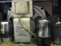
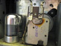
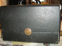
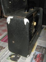
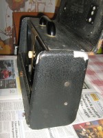
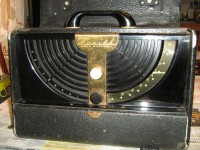
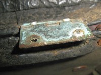
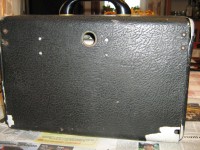
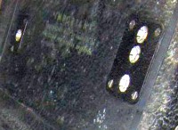
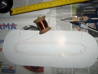
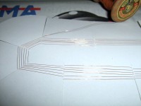
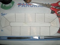
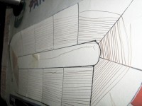
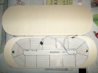
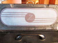
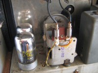
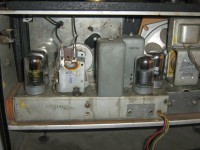
L'esemplare di 6G001 che ho acquistato in un mercatino era davvero in pessime condizioni. La pellicola nera che copriva il mobile era sfaldata in vari punti, una delle manopole non era originale e una delle cerniere del coperchio posteriore era divelta. Ma il problema più grave era che alla radio mancava l'antenna a telaio Wavemagnet. Le valvole invece erano tutte presenti e dopo la dovuta verifica con il Provavalvole TV-7 sono risultate anche efficienti. Mi sono rimboccato le maniche e per prima cosa ho provveduto a realizzare una nuova loop. Non avevo molte informazioni costruttive in merito, perciò mi sono inventato l'antenna. Ho ritagliato un cartoncino di forma ovale sul quale ho disegnato con il pennarello 13 "raggi" e usando del sottile filo di rame smaltato da 0,1 mm ho iniziato ad avvolgere delle larghe spire concentriche. Con un ago da lana bucavo il cartone, infilavo il filo, lo tendevo e passavo al "raggio" successivo. Una volta terminata la 16a spira e misurato 0,8 Ohm ai capi dell'avvolgimento, ho fissato il filo con del nastro adesivo e ho "nascosto" il loop tra due cartoni tagliati con le misure tratte "dall'impronta" che era rimasta all'interno del coperchio superiore della radio. Su uno dei cartoni ho incollato dei fogli di carta sui quali avevo provveduto a stampare l'aspetto della Wavemagnet originale. Poi ho collegato i sottili fili del telaio ai contatti che arrivano ai capi di C1 e di C2, ho avvitato l'antenna al legno del coperchio e sono passato alla fase successiva. La radio era stata costruita negli anni 40' e i componenti erano ancora quelli originali, perciò ho provveduto a sostituire i condensatori C18, C19, C20, C21 e C22 con componenti nuovi. Per non rovinare l'aspetto vintage sono riuscito a stipare i quattro nuovi condensatori elettrolitici (40, 20, 40 MF 400 VL e 200 MF 50 VL) dentro il cilindro che conteneva i vecchi componenti dopo averne asportato il contenuto. Per quanto riguarda invece il C22 l'ho sostituito con un condensatore in poliestere da 0,05 µF 600 VL. Dop aver alimentato la radio con un autotrasformatore dal quale ho spillato dapprima 50 Vac e poi 70 tenendo d'occhio la tensione sul piedino 2 della 3Q5GT (max 9Vdc che alimentano i filamenti in serie) e infine 110Vac senza notare effetti strani, ho provato a sintonizzare qualche stazione e con mio sommo stupore sono riuscito ad ascoltare RAI 1 di Venezia Campalto a 936 kHz. L'ultima fase del restauro è stato quella di eseguire una pulizia generale, usare l'apposito spray disossidante sul potenziometro del volume e sui contatti del selettore AC-BATT, di coprire con della vernice nera opaca le parti rovinate del mobile, sostituire le manopole con due di aspetto uguale trovate nel mio cassetto delle meraviglie e riavvitare la cerniera divelta. Finalmente una copia funzionante della Zenith 6G001 Universal è potuta entrare a far parte della mia collezione di radio. © IK3HIA, 2009. |
|||
 |
 |
 |
 |
 |
 |
 |
 |
 |
 |
 |
 |
 |
 |
 |
 |
|
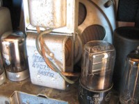
The 6G001 specimen that I bought in a flea market was in really bad condition. The black film that covered the cabinet was flaking in several places, one of the knobs was not original and one of the hinges on the back cover was torn off. But the biggest problem was that the radio was missing the Wavemagnet loop antenna. The valves, on the other hand, were all present and after due verification with the TV-7 tube tester they were also efficient. I rolled up my sleeves and first I proceeded to make a new loop. I didn't have much constructive information about it, so I invented the antenna. I cut out an oval-shaped cardboard on which I drew 13 "rays" with a sharpie and using thin enamelled 0.1 mm (38 AWG) copper wire I began to wind large concentric coils. With a wool needle I pierced the cardboard, threaded the thread, stretched it and moved on to the next "ray". Once the 16th turn was finished and I measured 0.8 Ohm at the ends of the winding, I fixed the wire with adhesive tape and I "hid" the loop between two cardboards cut with the measurements taken from the "footprint" that had remained inside inside the top cover of the radio. On one of the cartoons I glued some sheets of paper on which I had printed the aspect of the original Wavemagnet. Then I connected the thin loop wires to the contacts that arrive at the ends of C1 and C2, I screwed the antenna to the wood of the cover and proceeded to the next phase. The radio had been built in the 1940s and the components were still the original ones, so I proceeded to replace the capacitors C18, C19, C20, C21 and C22 with new components. In order not to spoil the vintage look, I managed to cram the four new electrolytic capacitors (40, 20, 40 MF 400 VL and 200 MF 50 VL) inside the cylinder that contained the old components after having removed the contents. As for the C22 instead, I replaced it with a 0.05 µF 600 VL polyester capacitor. After powering the radio with an autotransformer from which I first tapped 50 Vac and then 70 keeping an eye on the voltage on pin 2 of the 3Q5GT (max 9Vdc which feed the filaments in series) and finally 110Vac without noticing strange effects, I tried to tune in some stations and to my amazement I was able to listen to Venice's RAI 1 Campalto at 936 kHz. The last phase of the restoration was to perform a general cleaning, use the appropriate deoxidizing spray on the volume potentiometer and on the AC-BATT selector contacts, cover the damaged parts of the cabinet with matt black paint, replace the knobs with two of the same appearance found in my drawer of wonders and screw the torn hinge back on. Finally a working copy of the Zenith 6G001 Universal was able to become part of my radio collection. © IK3HIA, 2009. |
|||
|
Return to top of page
|
|||