 |
Arvin mod. 650P - U.S.A. 1952 |
|
|
|
Arvin mod. 650P - U.S.A. 1952 |
|
|
|
|||||
|
|
|
 |
Descrizione Restauro Schemi |
|
|
|
|
|||||
 |
 |
 |
 |
||
 |
 |
 |
 |
||
 Arvin
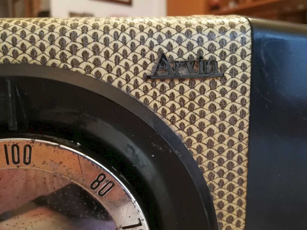
mod. 650P - U.S.A. 1952. Arvin
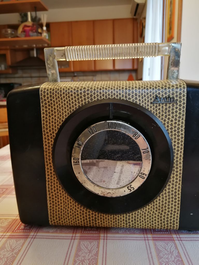
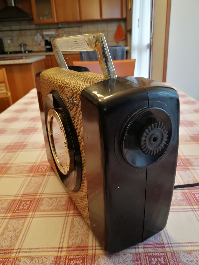
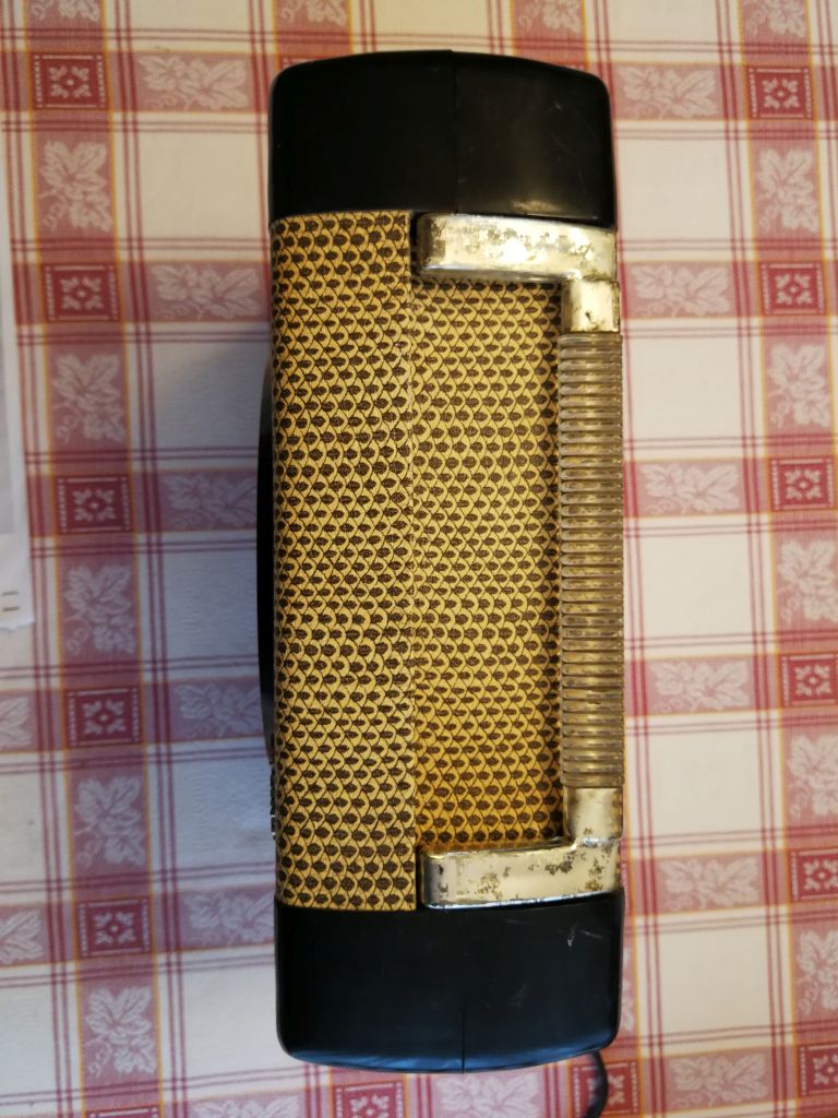
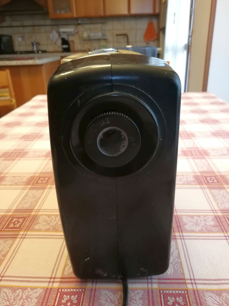
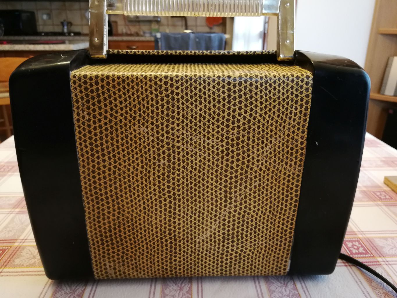
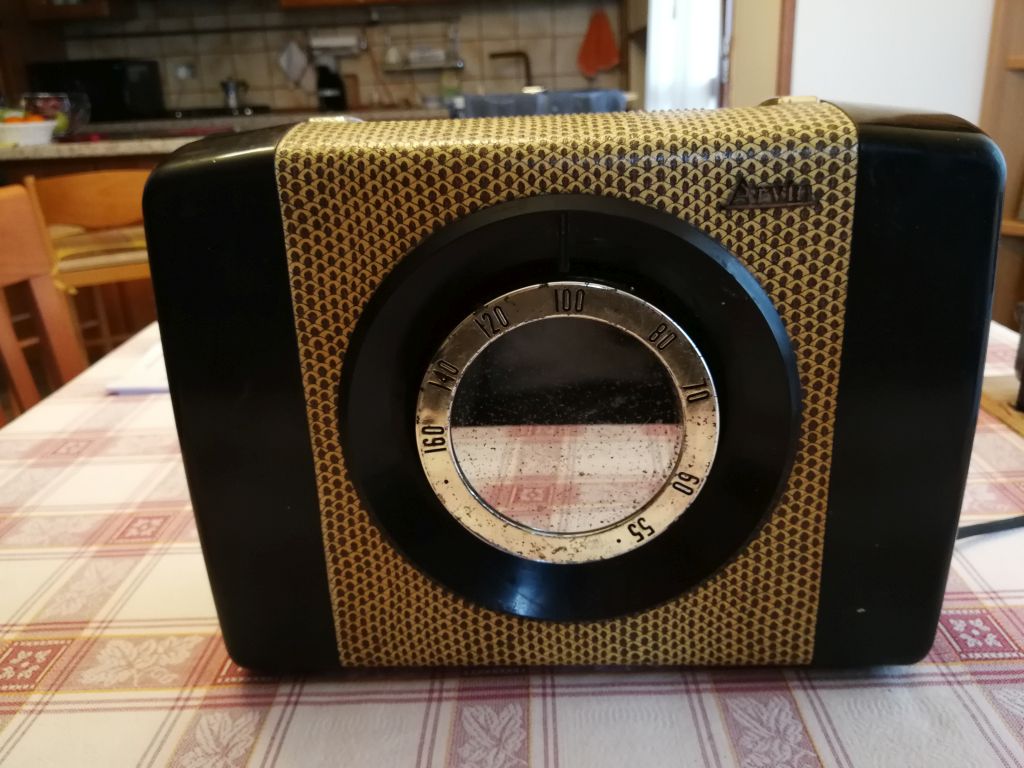
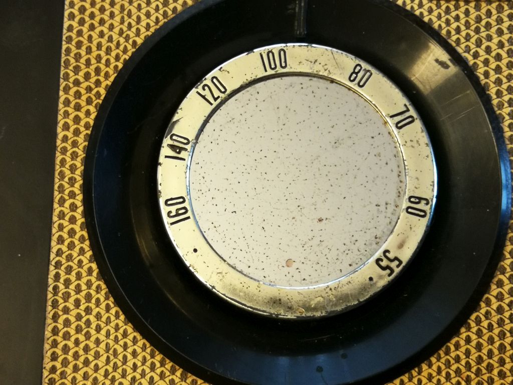
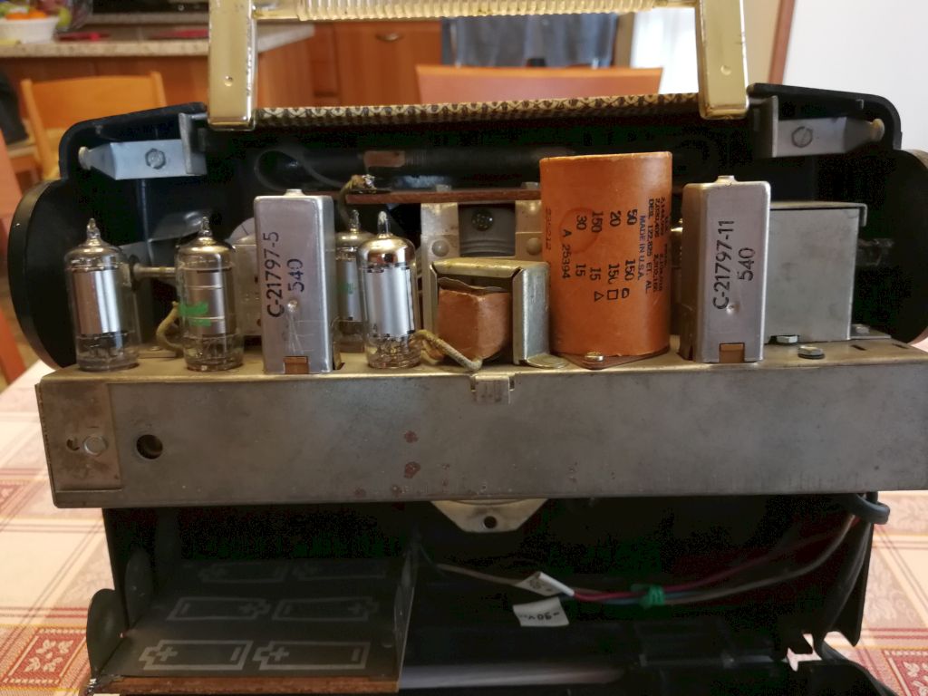
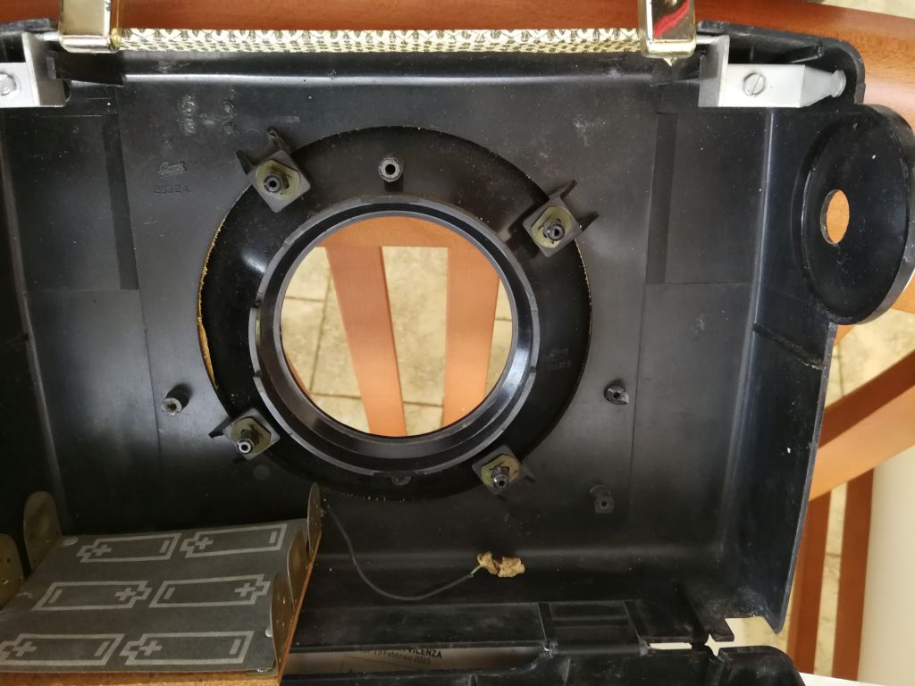
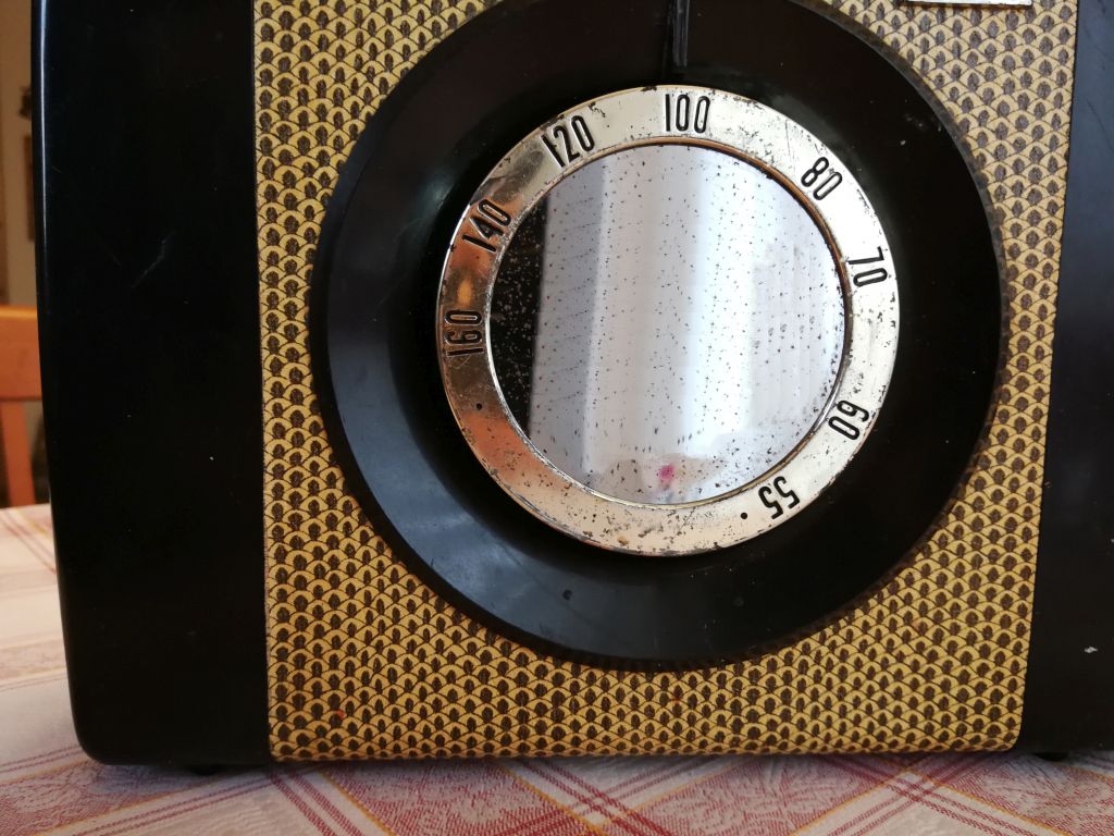
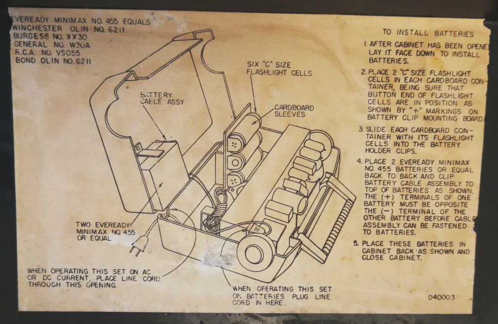
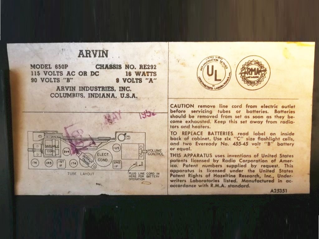
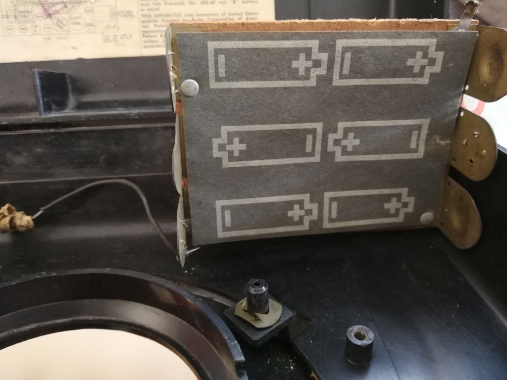
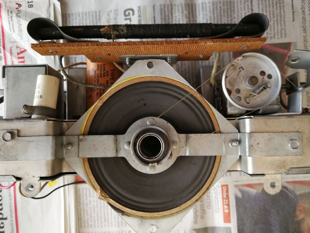
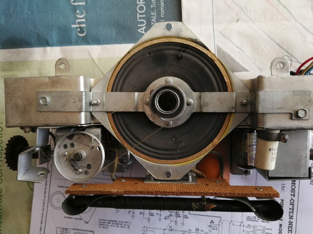
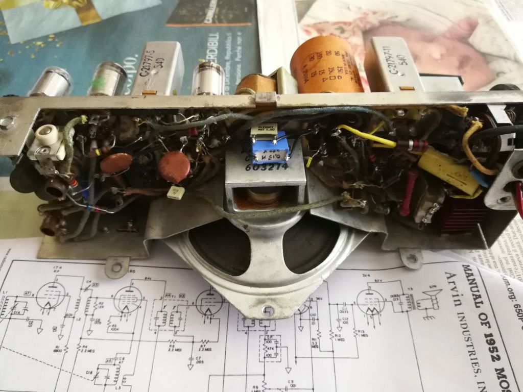
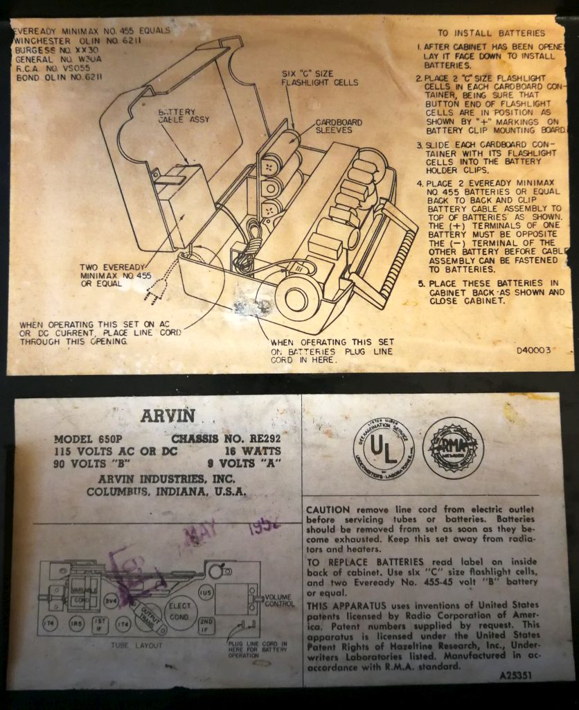
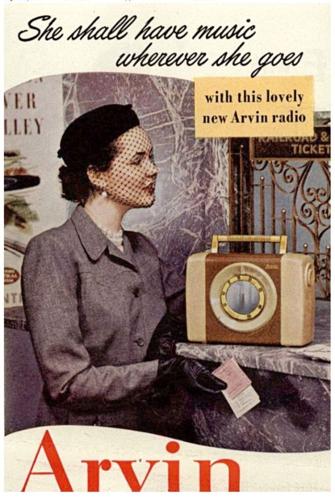
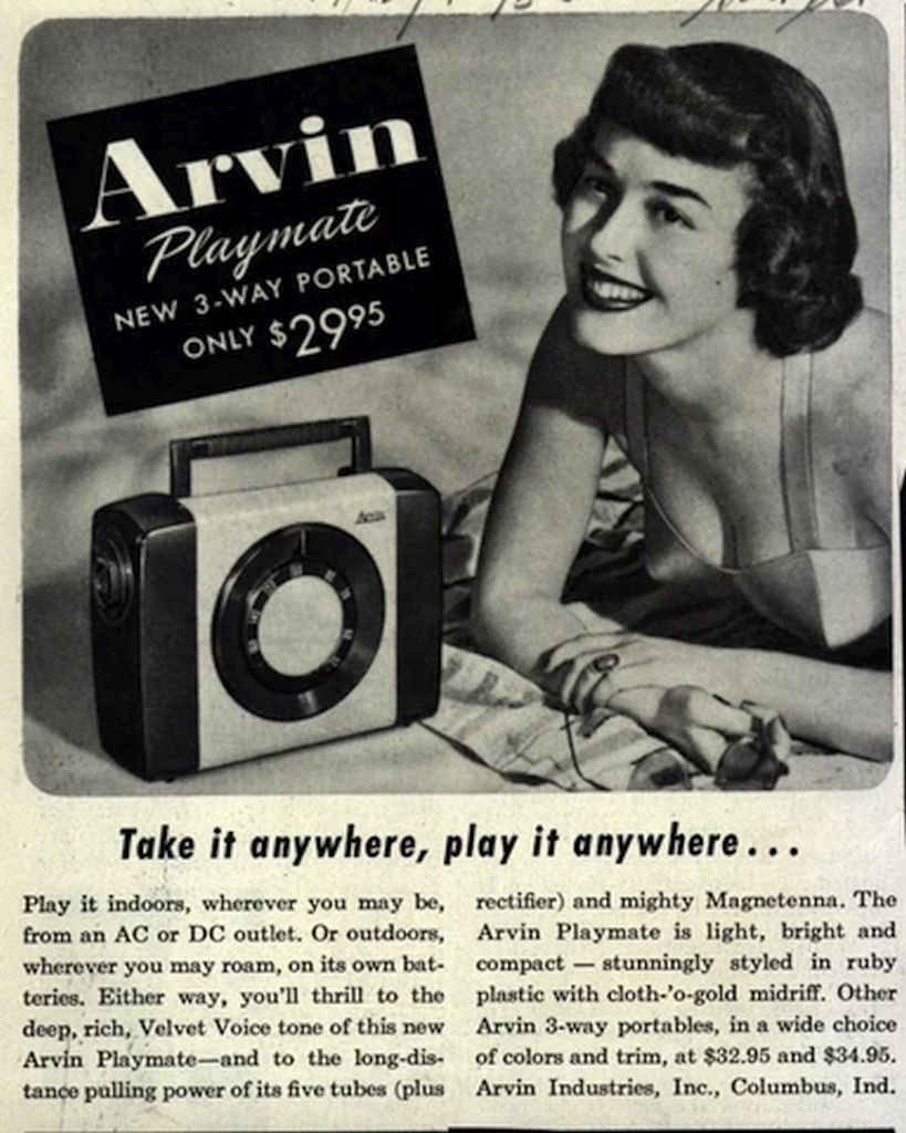
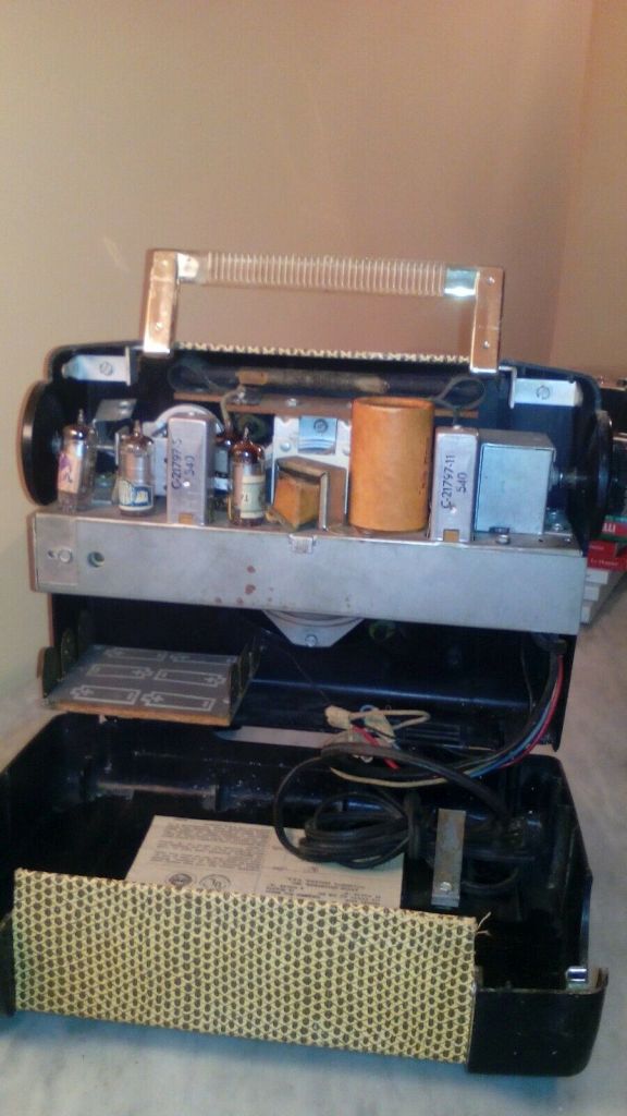
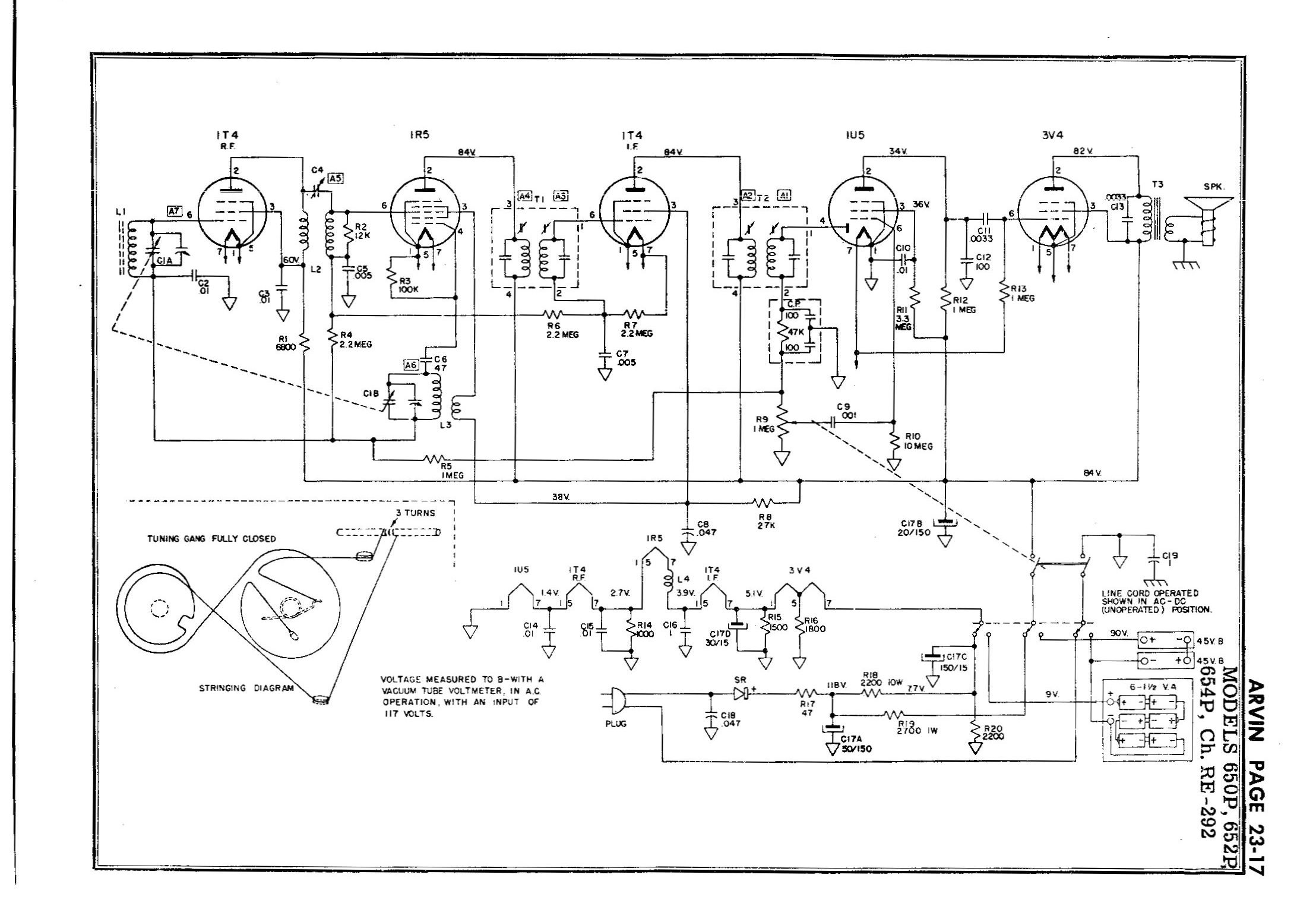
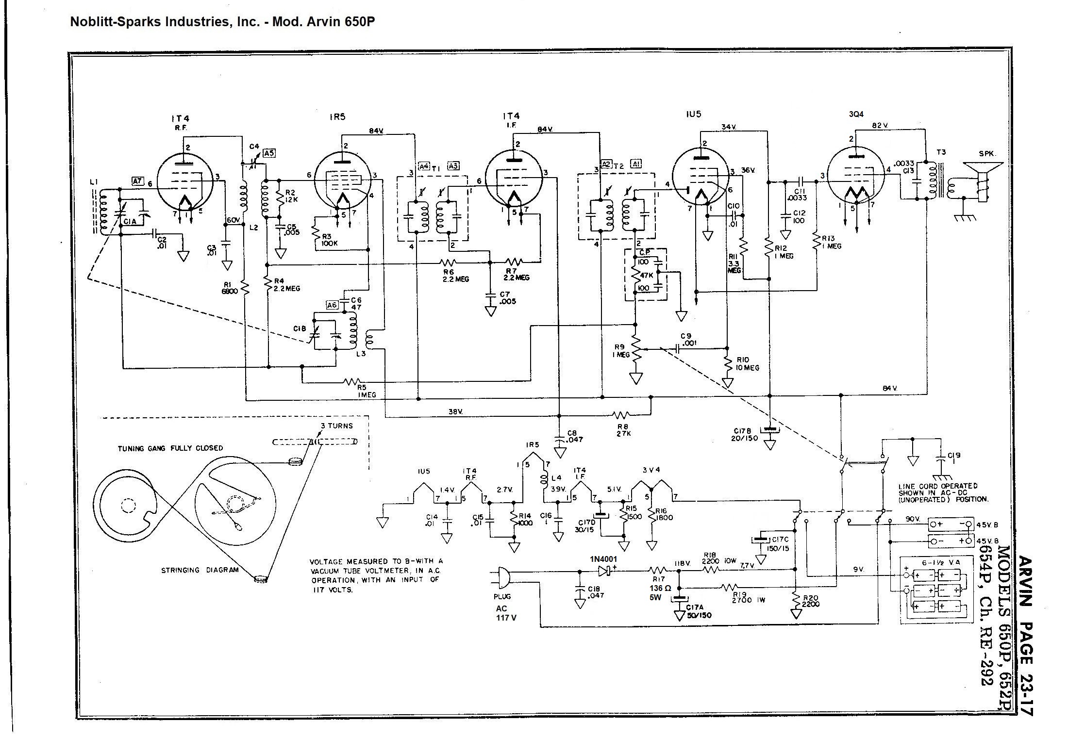
mod. 650P - U.S.A. 1952.Portable Medium Wave Receiver built and marketed in the early 1950s by Arvin Industries Inc. Columbus, Indiana, United States. The circuit is a superheterodyne using the valve series 1T4, 1R5, 1T4, 1U5, 3V4 (with heaters in series) and a selenium rectifier. In fact, the power supply can be supplied by 6 x 1.5 V type "C" batteries connected in series for the heaters and by two 45 V type Eveready 455 batteries connected in series for the anode (90 V total), or simply via the 110 VAC mains. When the radio is running on batteries, the mains cable is wound inside the cabinet and the plug is inserted into the appropriate socket visible on the chassis from the side of the volume potentiometer. This operation automatically switches the power to the batteries. The antenna is internal and is directional, in fact you have to rotate the radio looking for the best signal reception. This is one of the first examples of using a ferrite type antenna, with the winding made on a ferrite rod kept separate from the metal chassis by an elastic cardboard support to keep it locked and absorb shocks. With the batteries supplied, the radio has a good autonomy, and with the dual power supply it also has excellent operating versatility; the superheterodyne circuit also gives the device good sensitivity. The cabinet has a handle like a briefcase, with the central band worked in the likeness of snakeskin and the round tuning scale that has a mirror in the center. The elegant ensemble suggests that the entire device has been designed with special regard for a female user. Two labels are glued inside the rear cover, one explains how to insert and use the radio with batteries, the other shows the code with the model and the layout of the components on the chassis. The date of construction is impressed on this label, and in the item I restored the date was May 1952. IK3HIA © 2021 |
|||||
 |
 |
 |
 |
||
 |
 |
 |
 |
||
|
Back to the top of the page >>
|
|||||
|
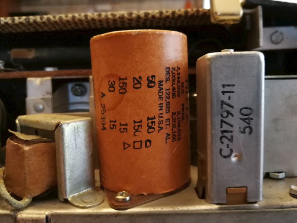
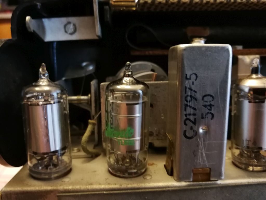
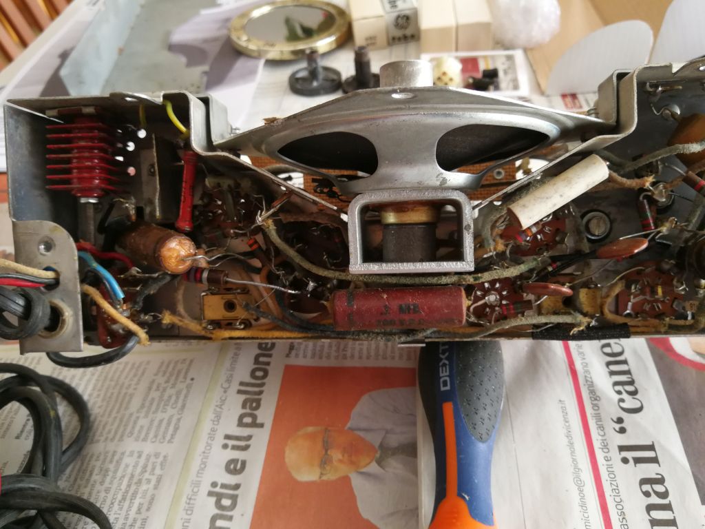
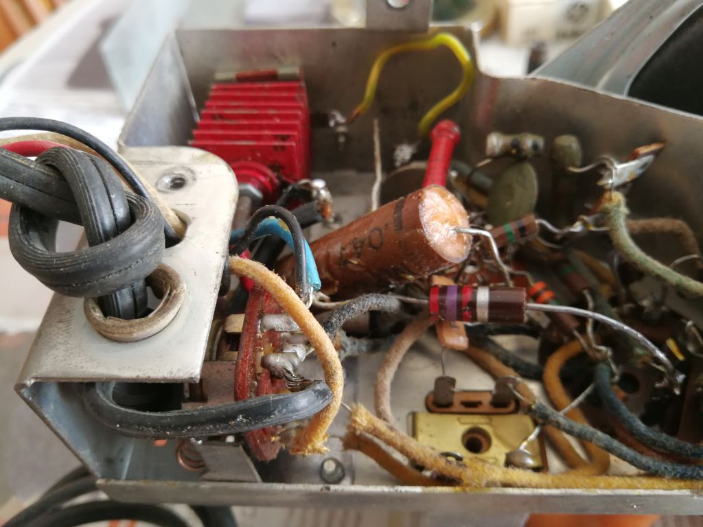
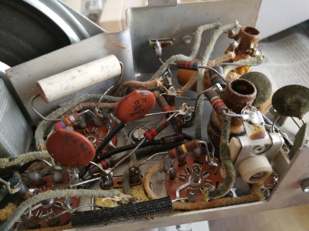
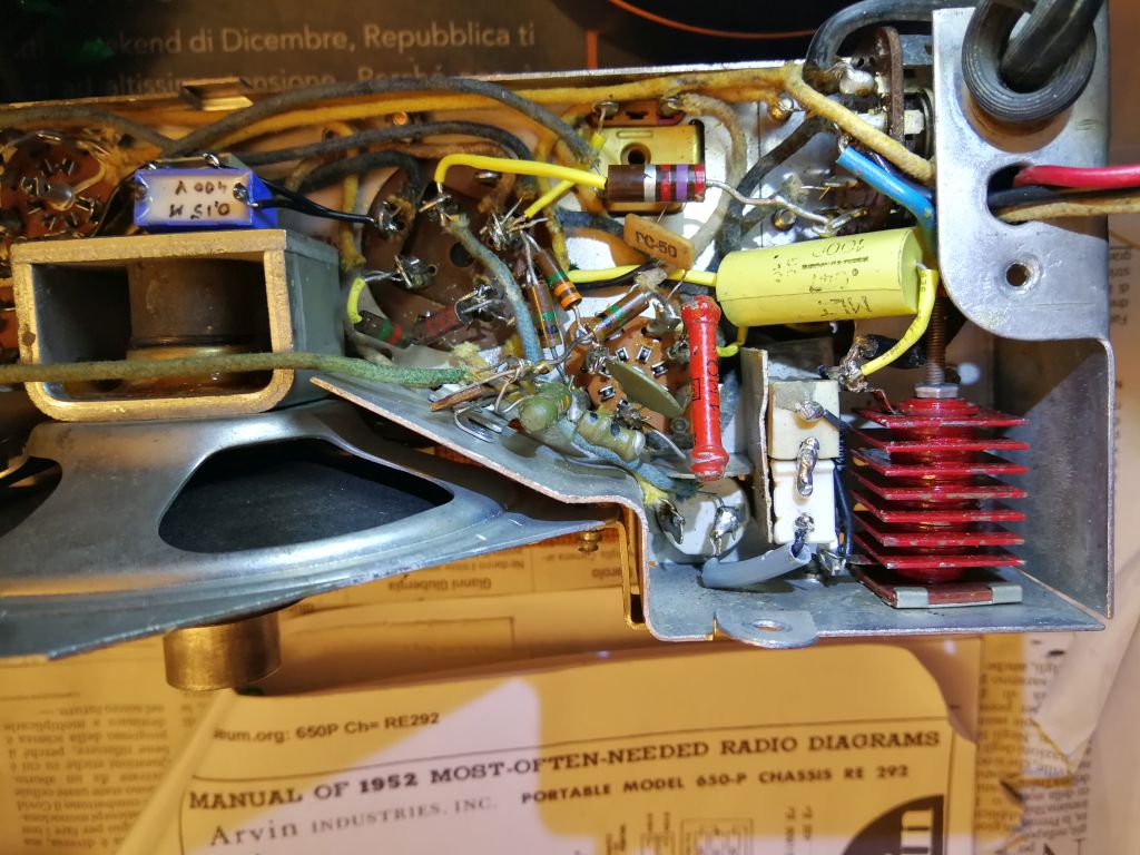
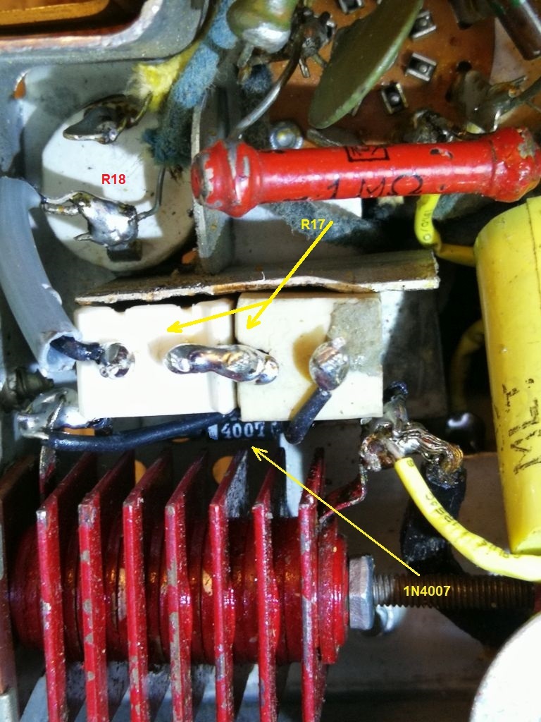
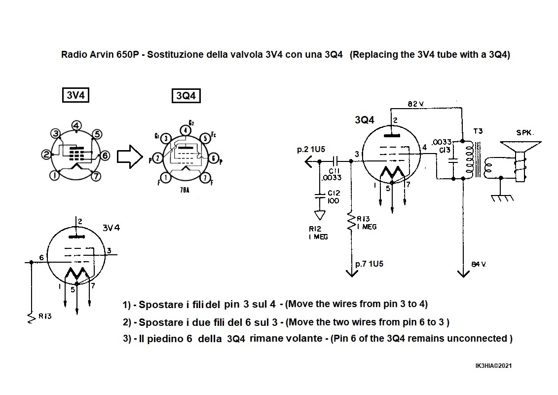
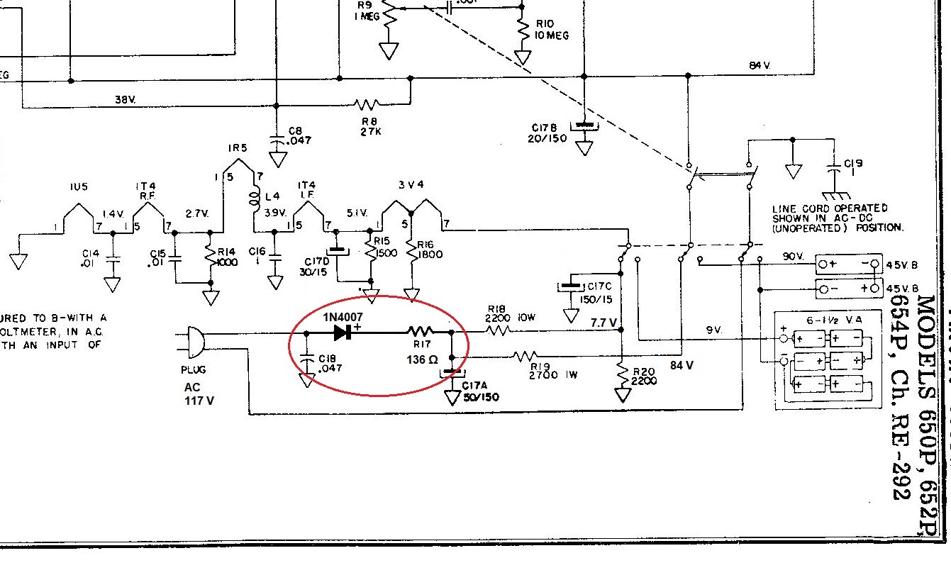
Restoration I received the radio not working with three of the five tubes (1T4, 1U5, 3V4) with the heater interrupted. An afternoon spent rummaging through valve boxes in my garage gave no results, but later I was able to buy the 1U5 and 1T4 online for a fair price. With the 3V4, on the other hand, I was not so lucky, I found few samples for sale and at exorbitant prices. After consulting the sacred texts and after some lucubrations I decided to use a 3Q4 that I had seen in a box of mine during previous searches. The two valves are equivalent with the same physical and electrical characteristics. The only difference is the arrangement of the electrodes on some pins. Once in possession of all the tubes I proceeded to verify their good functioning through my TV-7U tube tester, and checked that they were efficient I continued with the work. As my habit I started with the capacitors in the circuit. Arvin's electrolytic capacitors were all enclosed in the same container, an aluminum cylinder covered with brown cardboard. I made a drawing of the wires connected to the capacitor terminals and took some photos, then I proceeded to unsolder all the connections. Once the rivets that fixed it to the chassis were removed, the cardboard casing was separated from the aluminum and using a hacksaw I cut the cylinder on the circumference just above the base, uncovering it. I used the base of insulating material, the pre-existing terminals and the cardboard cylinder inside which I could insert a new 47 MF / 400 V capacitor for C17A, a 22 MF 400 V for C17B, a 400 MF 35V for C17C and a 50 MF / 35 V for C17D, all of such dimensions that they can be taped together inside the old casing. I also had to replace the paper capacitors C19, C16, C13, C11, C8 and C3 because they they had insulation losses I when measured them with my capacitor / ESR meter. I replaced them all with new components of equal capacity. The next step was to move the connections under the socket of the power output pentode to use a 3Q4 instead of the 3V4. The operation was very simple and ended with a few touches of soldering iron and tin. This link shows the changes to be made. At this point I inserted the radio mains plug into the socket located near the volume potentiometer. In this way the radio can be powered by batteries and for this purpose I was able to use the multivoltage power supply visible in this link. I connected the 9 V of the power supply to the light brown (+) and black (-) heaters wires, while the 90 V respectively to the red (+) and light blue (-) anodic wires. After a moment's hesitation, I flicked the power switch and the radio switch. A rustle came out of the loudspeaker, which increased as the volume turned up, then I turned the tuning knob and picked up the R.A.I. which broadcasts from Campalto (Venice) on 936 KHz. A quick retouch to the cores of the medium frequency transformers has strengthened the signal which has become even stronger by adjusting the compensator C4 placed between the first 1T4 and 1R5 with the special insulating screwdriver. It was five o'clock in the afternoon and by turning the variable capacitor I was able to listen to other stations, mostly foreign, but also two private radios that are active in Medium Wave in my area. The repair continued with the restoration of the power supply via the 110 V mains. The selenium rectifier measured with the tester had a few megohms at its ends and the high resistance remained so even by reversing the ohmmeter leads, so I thought about replacing the component with a modern 1N4007 silicon diode. To do this, I had to take into account the lower voltage drop that the diode introduced into the circuit. I started by replacing the 47 Ohm R17 with a ten Watt 250 Ohm resistor, powered the radio with 110 VAC and measured the voltage downstream of the 2200 Ohm R18. After a few attempts I came to find the optimal value which resulted in 136 Ohms (obtained with two ceramic resistors of 68 Ohm 5 W placed in series) and measuring at the ends of the electrolytic C17C with the voltmeter I verified that there were 7.7 VDC as was marked in the schematic. Powered with the mains the radio worked without hum and with a decent sound volume. For sentimental and aesthetic reasons I left the old red rectifier connected to selenium by welding the new diode to its ends, and nearby I also placed the two resistors in series which heat up a little and can take advantage of a piece of sheet metal and the holes present on the chassis to dissipate heat (the power supply new components are visible in this image). Finally, I treated the volume potentiometer with contact cleaner spray, covered the cracks on the speaker cone with two drops of glue and I screwed the chassis back into the cabinet. The repair had been completed successfully, and in this way I was able to put the Arvin 650P in my Radio collection. IK3HIA © 2021 |
|||||
 |
 |
 |
 |
||
 Arvin mod. 650P - U.S.A. 1952.
Ricevitore portatile in Onde Medie costruito e commercializzato nei primi anni 50 dalla Arvin Industries Inc. Columbus, Indiana, United States. Il circuito è una supereterodina che utilizza la serie di valvole 1T4, 1R5, 1T4, 1U5, 3V4 (con filamenti in serie) e un raddrizzatore al selenio. L'alimentazione infatti può essere fornita da 6 batterie da 1,5 V tipo "C" collegate in serie per i filamenti e da due da 45 V tipo Eveready 455 collegate in serie per l'anodica (90 V totali), oppure semplicemente tramite la rete elettrica a 110 Vca. Quando la radio funziona a batterie il cavo di rete va avvolto all'interno del cabinet e la spina va infilata nell'apposita presa visibile sullo chassis dal lato del potenziometro del volume. In tal modo si aziona automaticamente un interruttore che commuta l'alimentazione sulle batterie. L'antenna è interna ed è direzionale, infatti bisogna rotare la radio cercando la migliore ricezione del segnale. Questo è uno dei primi esempi di utilizzo di un'antenna tipo ferroxcube, con l'avvolgimento realizzato su una bacchetta di ferrite tenuta separata dallo chassis metallico tramite un supporto elastico di cartone per tenerla bloccato e ammortizzare gli urti. Con le batterie in dotazione la radio dispone di una buona autonomia, e con la doppia alimentazione ha anche un'ottima versatilità di funzionamento; il circuito supereterodina inoltre conferisce all'apparecchio una buona sensibilità. Il mobiletto ha la maniglia come una valigetta, è stampato in materiale plastico, con la la fascia centrale lavorata a somiglianza di pelle di serpente e la scala di sintonia rotonda che ha nel centro uno specchio. L'insieme elegante suggerisce che tutto l'apparecchio sia stato disegnato con speciale riguardo a un utilizzatore di sesso femminile. All'interno del coperchio posteriore sono incollati due etichette, una spiega come effettuare l'inserimento e l'utilizzo della radio con le batterie, mentre l'altra riporta la sigla con il modello e la disposizione dei componenti sullo chassis. Su quest'ultima etichetta è impressa la data di costruzione che nell'esemplare che ho restaurato è Maggio 1952. IK3HIA©2021 |
|||||
|
Back to the top of the page >>
|
|||||
 |
 |
 |
 |
||
|
Restauro La radio mi è pervenuta non funzionante con tre delle cinque valvole (1T4, 1U5, 3V4) con il filamento interrotto. Un pomeriggio trascorso a rovistare nelle scatole di valvole che ho in garage non ha dato risultati, ma più tardi sono riuscito ad acquistare in rete per un prezzo onesto la 1U5 e la 1T4. Con la 3V4 invece non sono stato altrettanto fortunato, ho trovato pochi esemplari in vendita e a prezzi esosi. Dopo aver consultato i sacri testi e dopo alcune elucubrazioni ho deciso di utilizzare una 3Q4 che avevo visto in una mia scatola durante le precedenti ricerche. Le due valvole sono equivalenti con le stesse caratteristiche fisiche ed elettriche. L'unica differenza è la disposizione degli elettrodi su alcuni piedini. Una volta in possesso di tutte le valvole ho provveduto a verificarne il buon funzionamento tramite il mio provavalvole TV-7U, e una volta controllato che erano efficienti ho proseguito con il lavoro. Come mia abitudine ho iniziato dai condensatori presenti nel circuito. I condensatori elettrolitici dell'Arvin erano tutti racchiusi nello stesso contenitore, un cilindro di alluminio ricoperto di cartone marrone. Ho eseguito un disegno dei fili collegati ai terminali del condensatore e ripreso delle foto, poi ho provveduto a dissaldare i collegamenti. Una volta tolti i rivetti che lo fissavano allo chassis, l'involucro di cartone del componente si è separato dall'alluminio e usando un seghetto ho tagliato il cilindro sulla circonferenza poco sopra la base scoperchiandolo. Ho utilizzato la base di materiale isolante, i terminali preesistenti e il cilindro di cartone al cui interno ho potuto inserire un condensatore nuovo da 47 MF/400 V per C17A, un 22 MF 400 V per C17B, un 400 MF 35V per C17C e un 50 MF/35 V per C17D, tutti di dimensioni tali poter stare nastrati assieme all'interno del vecchio involucro. Ho dovuto sostituire anche i condensatori a carta C19, C16, C13, C11, C8 e C3 perché isolandoli e misurandoli con il mio capacimetro/ESR meter presentavano delle perdite. Li ho sostituiti tutti con componenti nuovi di pari capacità. Il passaggio seguente è stato lo spostamento delle connessioni per poter utilizzare la 3Q4 al posto della 3V4. L'operazione è stata molto semplice e si è conclusa con con pochi tocchi di saldatore e stagno. Questo link mostra le modifiche da effettuare. A questo punto ho infilato la spina di rete della radio nell'apposita presa posta vicino al potenziometro del volume. In tal modo la Radio può essere alimentata con le batterie e all'uopo ho potuto utilizzare l'alimentatore multitensione visibile in questo link. I 9 V dell'alimentatore li ho collegati ai fili marrone chiaro (+) e nero (-) dei filamenti, mentre i 90 V rispettivamente ai fili rosso (+) e celeste (-) dell'anodica. Dopo un momento di esitazione ho azionato l'interruttore dell'alimentatore e quello della radio. Dall'altoparlante è uscito del fruscio, che è aumentato alzando il volume, poi ho ruotato la manopola di sintonia e ho captato la stazione R.A.I. che trasmette da Campalto (Venezia) sui 936 KHz. Un rapido ritocco ai nuclei dei trasformatori di media frequenza ha irrobustito il segnale il quale è diventato ancora più forte regolando con l'apposito cacciavite isolante il compensatore C4 posto tra la prima 1T4 e la 1R5. Erano le cinque del pomeriggio e ruotando il condensatore variabile ho potuto ascoltare altre stazioni, per lo più straniere, ma anche due radio private che sono attive in Onde Medie nella mia zona. La riparazione è continuata con il ripristino dell'alimentazione tramite rete a 110 V. Il raddrizzatore al selenio misurato con il tester presentava alcuni megaohm ai suoi capi e l'alta resistenza rimaneva tale anche invertendo i puntali dell'ohmmetro, pertanto ho pensato di sostituire il componente con un moderno diodo al silicio 1N4007. Per fare ciò ho dovuto tener conto della minore caduta di tensione che il diodo introduceva nel circuito. Ho iniziato sostituendo la R17 da 47 Ohm con una resistenza da 250 Ohm da una decina di Watt, ho alimentato la radio con 110 VAC e misurato la tensione a valle della R18 da 2200 Ohm. Dopo alcuni tentativi sono arrivato a trovare il valore ottimale che è risultato di 136 Ohm (ottenuti con due resistenze in ceramica da 68 Ohm 5 W poste in serie) e misurando ai capi dell'elettrolitico C17C con il voltmetro ho verificato che ci fossero i 7.7 V continui come da schema. Alimentata in alternata a 110 V la radio funzionava senza ronzii e con un discreto volume sonoro. Per motivi sentimentali ed estetici ho lasciato collegato il vecchio e rosso raddrizzatore al selenio saldando ai suoi capi il nuovo diodo, e lì vicino ho sistemato anche le due resistenze in serie le quali scaldano un po' e possono usufruire di un pezzo di lamiera e dei fori presenti sullo chassis per dissipare il calore (in questa immagine sono visibili i componenti aggiunti nell'alimentatore). Per finire ho trattato il potenziometro del volume con lo spray pulisci contatti, ho ricoperto con due gocce di attaccatutto le crepe presenti sul cono dell'altoparlante e ho riavvitato lo chassis nel mobiletto. La riparazione si era conclusa con successo, e in tal modo potevo inserire l'esemplare dell'Arvin 650P nella mia collezione di Radio. IK3HIA©2021 |
|||||
 |
 |
 |
 |
||
| Schematics
and modifications |
|||||
 |
 |
 |
 |
||
|
Back to the top of the page >>
|
|||||