 |
Hallicrafters mod. S-53A U.S.A. - 1951 |
 |
|
|
Hallicrafters mod. S-53A U.S.A. - 1951 |
|
|
|
 |
Descrizione
Restauro |
|
|
|
|||
 |
 |
 |
 |
 |
 |
 |
 |
|
Questo ricevitore era stato progettato per operare nelle Onde Corte e nella banda dei 6 metri in Ampiezza Modulata (AM) e in Telegrafia (CW) con cinque gamme, selezionabili con il comando Band Selector, che coprivano le seguenti porzioni di frequenza: (A) da 0,540 a 1.63MHz, (B) da 2,5 a 6,3MHz, (C) da 6,3 a 16,0MHz, (D) da 14,0 a 31 MHz ed (E) da 48 a 54,5MHz con una lacuna in ricezione da 1,63 a 2,5 MHz. La scala di sintonia è rettangolare con la parte superiore suddivisa in cinque fascie tante sono le bande di frequenza, la parte inferiore invece è relativa al comando allargatore di banda. Il circuito della S-53 è una supereterodina a singola conversione che utilizza 8 valvole con zoccolo noval e octal: 6BA6 (miscelatore), 6C4 (oscillatore), 6BA6 (1° ampl. FI), 6BA6 (2° ampl. FI), 6H6 (rivelatore), 6SC7 (preampl. BF e BFO); 6K6GT (amplificatore BF); 5Y3GT (raddrizzatrice). Le due lampadine che illuminano la scala sono del tipo Mazda #44 (6,3 V, 250 mA con attacco a baionetta). Sul pannello frontale i comandi da sinistra a destra e dall'alto in basso sono i seguenti: Band Spread (allargatore di banda), sintonia, Standby-Receive (serve per zittire l'S-53 quando è utilizzato con un trasmettitore), Band Selector, CW-AM, Sensitivity (sensibilità), Noise Limiter on-off (limitatore di disturbi), High-Low Tone (controllo di tono). Il mobile è metallico con il coperchio incernierato posteriormente e aprendolo si ha un facile accesso allo chassis per un'eventuale manutenzione come ad esempio la sostituzione di una valvola esaurita o una taratura. Nella parte posteriore da sinistra a destra c'è il cavo di alimentazione, una presa RCA fono, l'interruttore che esclude l'altoparlante interno, la presa bipolare per cuffie ad alta impedenza (da 500 a 3000 Ohm), e la morsettiera per Antenna e Terra. Le dimensioni del mobile sono: 32,5 x 17,8 x 19,7 cm e il peso è di 8.2 kg. La morsettiera per l'antenna ha tre morsetti: A1, A2 e G. Se si dispone di un'antenna monofilare la si collega ad A1 e A2 viene cortocircuitato con G che va collegato a massa. I capi del cavo coassiale di un'antenna dipolo invece vanno connessi ai morsetti A1 e A2. L'alimentazione dell'S-53A è a 110 Vac a 50 - 60 Hz ed avviene tramite trasformatore, così lo chassis è isolato dalla rete elettrica e non si corre il pericolo di fulminarsi inavvertitamente. Con una antenna esterna collegata la sensibilità è piuttosto buona nelle Onde Corte, ma il BFO non si può regolare, va bene per rivelare i segnali in telegrafia (CW) ma risulta molto difficile se non impossibile sintonizzare i segnali in Banda Laterale Unica (SSB) utilizzati oggigiorno dai radioamatori. © IK3HIA, 2008. |
|||
 |
 |
 |
 |
|
This receiver was designed to operate in the Short Wave and 6 meter band in Amplitude Modulated (AM) and in Telegraphy (CW) with five bands, selectable with the Band Selector control, which covered the following frequency portions: (A) from 0.540 to 1.63 MHz, (B) from 2.5 to 6.3 MHz, (C) from 6.3 to 16.0 MHz, (D) from 14.0 to 31.0 MHz and (E) from 48.0 to 54.5 MHz with a reception gap of 1.63 at 2.5 MHz. The tuning scale is rectangular with the upper part divided into five bands, as many as the frequency bands, the lower part is related to the band widener control. The S-53 circuit is a single conversion superheterodyne that uses 8 valves with noval and octal sockets: 6BA6 (mixer), 6C4 (oscillator), 6BA6 (1st FI amplifier), 6BA6 (2nd FI amplifier), 6H6 (detector), 6SC7 (BF and BFO preamp); 6K6GT (BF amplifier); 5Y3GT (rectifier). The two lamps that illuminate the dial are Mazda #44 type (6.3 V, 250 mA with bayonet mount). On the front panel the controls from left to right and from top to bottom are as follows: Band Spread (band spreader), tuning, Standby-Receive (used to silence the S-53 when used with a transmitter), Band Selector, CW-AM, Sensitivity, Noise Limiter on-off (noise limiter), High-Low Tone (tone control). The cabinet is metal with the lid hinged at the rear and opening it gives easy access to the chassis for any maintenance such as replacing a worn tube or a calibration. On the rear from left to right there is the power cable, an RCA phono socket, the switch that excludes the internal speaker, the two-pole socket for high impedance headphones (from 500 to 3000 Ohm), and the terminal block for Antenna and Earth. The dimensions of the cabinet are: 12.8 x 7 x 7.75 inch and the weight is 18 lb 1 oz. The antenna terminal block has three terminals: A1, A2 and G. If you have a monofilament antenna, connect it to A1 and A2 is short-circuited with G which is connected to ground. The ends of the coaxial cable of a dipole antenna instead are connected to terminals A1 and A2. The S53 is powered at 110 Vac at 50 - 60 Hz and is via a transformer, so the chassis is isolated from the electrical network and there is no risk of inadvertent electrocution. With an external antenna connected the sensitivity is quite good in Short Waves but the BFO cannot be adjusted, it is good for detecting telegraphy (CW) signals but it is very difficult if not impossible to tune the Single Sideband (SSB) signals used nowadays by radio amateurs. © IK3HIA, 2008. |
|||
 |
 |
 |
 |
|
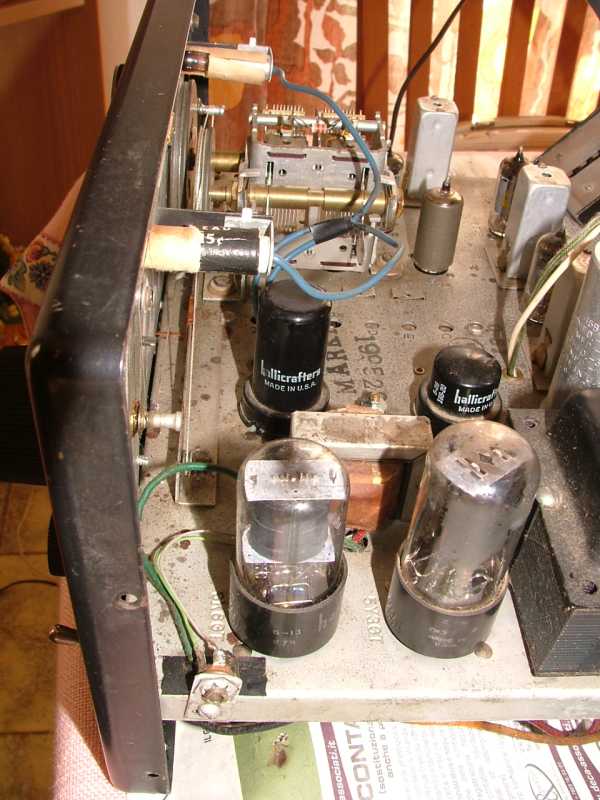
The first work to get the radio back up and running was to rejuvenate the quadruple electrolytic capacitor C57A, B, C and D by emptying it of its old content and inserting three new capacitors of 50, 10, 10 MF 400 VL and one of 25 MF 50 VL. Then I checked the efficiency of all the valves with my TV-7U tube tester and replaced the 6K6 and the 5Y3 as they were exhausted. After using the deoxidizing spray on the two potentiometers and on the switches, I powered the radio via a 220 to 120 Vac transformer, and I measured the anode voltage of 250 Vdc on pin 8 of the 5Y3. At this point I connected a dipole antenna, selected the C band, chose CW mode, turned the Sensitivity knob fully clockwise and tuned in some ham stations transmitting in Morse code on 7 MHz. After checking the operation of the other frequency bands, no further action or adjustment was necessary. © IK3HIA, 2008. |
|||
 |
 |
 |
 |
|
Il primo lavoro fatto per rimettere in funzione la radio è stato quello di ringiovanire il condensatore elettrolitico quadruplo C57A, B, C e D svuotandolo del vecchio contenuto e infilandoci dentro tre condensatori nuovi da 50, 10, 10 MF 400 VL e uno da 25 MF 50 VL. Poi ho controllato l'efficienza di tutte le valvole con il mio provavalvole TV-7U e ho sostituito la 6K6 e la 5Y3 in quanto risultavano esaurite. Dopo aver usato lo spray disossidante sui due potenziometri e sui commutatori ho alimentato la radio tramite un trasformatore da 220 a 120 Vac, e ho misurato la tensione anodica di 250 Vdc sul piedino 8 della 5Y3. A questo punto ho collegato un'antenna a dipolo, ho selezionato la gamma C, ho scelto la modalità CW, ho girato la manopola Sensitivity completamente in senso orario e ho sintonizzato alcune stazioni di radioamatori che trasmettevano in alfabeto morse sui 7 MHz. Dopo aver controllato il funzionamento delle altre bande di frequenza non sono servite ulteriori azioni o regolazioni. © IK3HIA, 2008. |
|||
 |
 Dial cords |
 Schematic diagram |
 Service manual |
|
|
Return to: ik3hia home page |
|
Return to Old Ham radio page |