 |
Hallicrafters mod. S-38A U.S.A. - 1949 |
 |
|
|
Hallicrafters mod. S-38A U.S.A. - 1949 |
|
|
|
 |
Descrizione
Restauro |
|
|
|
|||
 |
 |
 |
 |
 |
 |
 |
 |
|
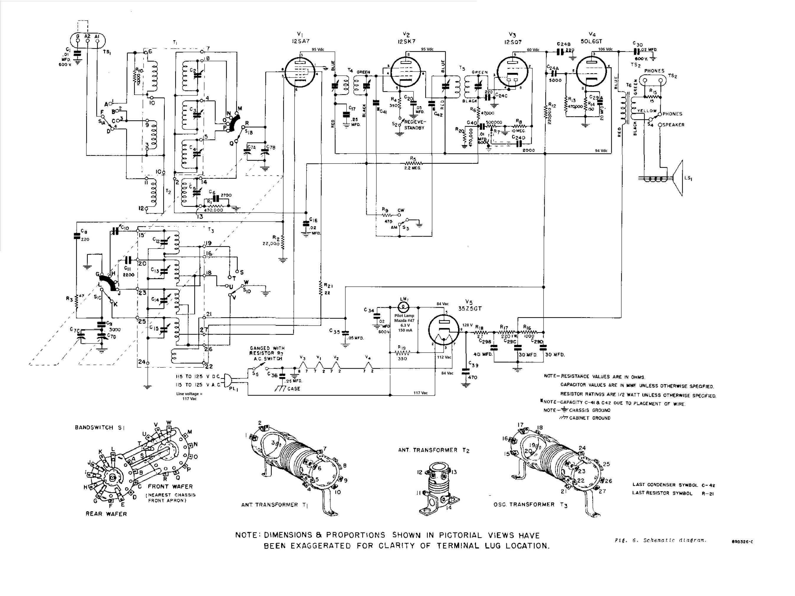
La forma del mobile metallico era stata disegnata dallo stilista industriale Raymond Lowey e fu utilizzata dal modello S-38 fino al S-38C nel 1954, quando la fabbrica mise in produzione l'S-38D nel quale le due scale parlanti a semicerchio furono sostituite da un'ampia scala di sintonia rettangolare. Il circuito del ricevitore era una supereterodina a singola conversione che utilizzava 5 valvole octal: 12SA7, 12SK7, 12SQ7, 50L6GT, 35Z5GT. La copertura di frequenza andava da 550 kHz a 30 Mhz suddivisa in quattro bande, con Frequenza Intermedia a 455 kHz. Le quattro bande erano così suddivise: 550÷1650 kHz - 1,65÷5.0 - 5,0÷14,5 - 13,5-32 MHz. I modi di ricezione erano due: AM e CW (Ampiezza Modulata e Onda Continua), e la radio era dotata di BFO (generatore di battimento) che permetteva la rivelazione dei segnali CW in alfabeto Morse. Grazie al BFO e al comando allargatore di banda la radio è in grado di rivelare anche i segnali SSB (Banda laterale Unica / Single Side Band) utilizzati oggigiorno dai radioamatori di tutto il mondo. La potenza di 2,1 Watt in uscita della 50L6 e l'altoparlante da 12,7 cm / 5 inch e 3,2 Ohm fornivano un ottimo segnale audio. La lampadina che illuminava la scala parlante era da 6 - 8 V e l'alimentazione della radio poteva avvenire indifferentemente in corrente continua o in alternata da 105 a 125 V, il consumo era di 30 Watt max, le dimensioni erano: 33 x 17 x 19,5 cm e il peso dell'apparato era di 5 Kg. La radio era molto sensibile e con la sintonia allargata (band spread) oltre alle stazioni broadcasting in Onde Medie permetteva di sintonizzare con facilità e precisione i deboli segnali dei radioamatori nelle tre gamme di Onde Corte, inoltre era dotata di ALC (controllo automatico di volume), di interruttore "Stand by" per l'utilizzo con un trasmettitore e di presa per cuffie ad alta impedenza (da 500 a 2000 Ohm). © IK3HIA, 2005. |
|||
|
|
|||
 |
 |
 |
 |
 |
 |
 |
 |
|
The shape of the metal cabinet was designed by industrial designer Raymond Lowey and was used from the S-38 model up to the S-38C in 1954, when the factory put into production the S-38D in which the two semicircular dials were replaced by a large rectangular tuning scale. The receiver circuit was a single conversion superheterodyne using 5 octal tubes: 12SA7, 12SK7, 12SQ7, 50L6GT, 35Z5GT. The frequency coverage ranged from 550 kHz to 30 MHz divided into four bands, with an Intermediate Frequency at 455 kHz. The four bands were divided as follows: 550÷1650 kHz - 1.65÷5.0 - 5.0÷14.5 - 13.5-32 MHz. There were two reception modes: AM and CW (Amplitude Modulation and Continuous Waves), and the radio was equipped with a BFO (Beat Frequency Oscillator) that allowed the detection of Morse code signals. Thanks to the BFO and the band spread knob, the radio is also able to detect the SSB (Single Side Band) signals used nowadays by radio amateurs all over the world. The 50L6's three Watt output power and the 5 inch 3.2 Ohm speaker provided an excellent audio signal. The light that illuminated the dial was a 6 - 8 V lamp and the radio could be powered indifferently in direct current or in alternating current from 105 to 125 V. The consumption was 30 Watt max, the dimensions were: 13 x 6.7 x 7.7 inch and the weight of the apparatus was 11.02 lb. The radio was very sensitive and with the wide tuning (band spread) in addition to the broadcasting stations in Medium Waves it allowed to tune with ease and precision the weak signals of the radio amateurs in the three bands of Short Waves, it was also equipped with ALC (Automatic Level Control), a "Stand by" switch for use with a transmitter and a socket for high impedance headphones (from 500 to 2000 Ohm). © IK3HIA, 2005. |
|||
|
Click on the images to enlarge
|
|||
 |
 |
 |
 |
|
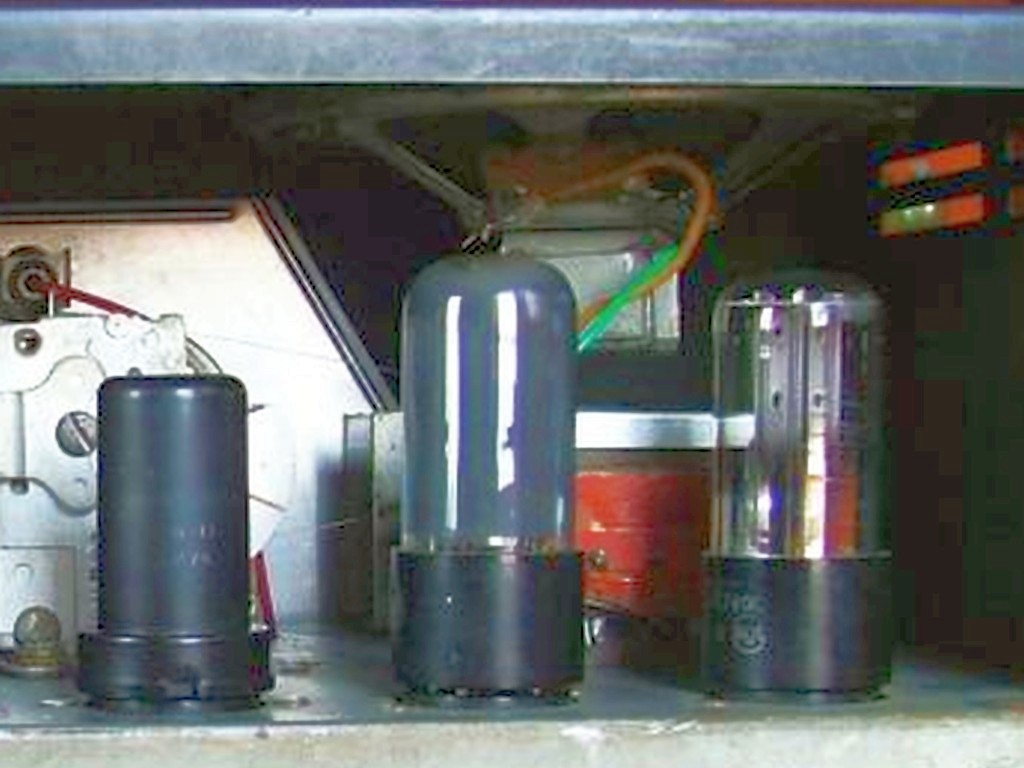
Qualche giorno dopo ho fissato all'asse del potenziometro del volume una manopola di fortuna, ho collegato la radio a un trasformatore da 220 Vac a 110 Vac, l'ho accesa e ho constatato che il venditore aveva ragione, la S-38A non dava proprio nessun segno di vita. Staccata l'alimentazione l'ho aperta, ho estratto lo chassis e ho sfilato con cautela le valvole dagli zoccoli per misurare a tutte la continuità del filamento. Quattro valvole avevano il filamento integro, quello della raddrizzatrice 35Z5 invece era interrotto. Ho ipotizzato che qualche intelligentone avesse connesso il cavo di rete ai 220 Vac anziché ai 110 necessari e la valvola raddrizzatrice aveva fatto da fusibile bruciandosi. Come ad avallare questa ipotesi ho trovato che anche la lampada pilota era bruciata, pertanto bisognava sostituirle entrambe. In garage ho scatole con valvole di tutti i tipi e fortunatamente in una ho rintracciato la 35Z5GT che mi serviva, la lampadina invece si è rivelata un problema. La lampadina pilota bruciata era da 6,3 V 150 mA con l'attacco a baionetta mentre nella mia scatola di lampadine da 6,3 V 150 mA ne avevo molte con attacco a vite edison E10, quelle usate nelle scale parlanti delle radio europee, nessuna tipo #47 a baionetta. Potevo girare per i negozi in cerca della lamoadina giusta ma, il mio istinto del fai da te ha avuto la meglio, ho rotto il vetro della lampada bruciata e dopo aver con pazienza dissaldato e recuperato con qualche difficoltà il bulbo di una lampadina E10 ho eseguito il trapianto con successo. Mi sono trattenuto dal riaccendere subito la radio, mi rendevo conto che i condensatori elettrolitici erano molto datati e che era consigliabile sostituirli. Anche in questo caso è servita un po' di pazienza per svuotare del contenuto il condensatore multiplo originale C29 che conteneva quattro capacità: 40 MF 160 VL, 30 MF + 30 MF 150 VL e 20 MF 25 VL. I componenti moderni sono molto piccoli e nelle mie scatole ho trovato quattro condensatori con capacità abbastanza simili e con tensione di lavoro più elevata che potevano entrare nel vecchio involucro. I poli negativi dei condensatori (47, 33, 33 MF 250 VL e 22 MF 50 VL) li ho collegati tutti assieme a un filo nero, mentre i positivi a fili di diverso colore, poi ho chiuso l'involucro con un po' di cera rubata a una candela, ho saldato i vari terminali al circuito e ho collegato l'altoparlante. A questo punto con un po' di trepidazione ho selezionato la banda broadcasting, ho collegato un'antenna e ho alimentato la radio con 110 V. Dopo qualche istante dall'altoparlante è uscito dapprima un po' di ronzio poi il rumore di fondo e agendo sulla manopola di sintonia ho captato il forte segnale della stazione RAI che nella mia zona trasmette a 936 kHz. Tutte le gamme di frequenza sono risultate funzionanti e dopo aver effettuato l'allineamento dei trasformatori di Frequenza Intermedia a 455 kHz con il mio oscillatore modulato Heathkit IG-102, ho rintracciato nel mio cassetto delle meraviglie una manopola rotonda, abbastanza simile a quella del cambio gamma, l'ho inserita sull'asse del comando volume e ho concluso la riparazione. © IK3HIA, 2005 |
|||
 |
 |
 |
 |
 |
 |
 |
 |
|
|
|||
|
|
Return to: ik3hia home page |
|
Return to Old Ham radio page |