 |
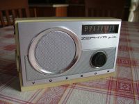
VOXSON Zephyr
5th mod. 765 Italy 1967 |
 |
|
|
Italiano
|
||
|
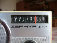
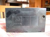
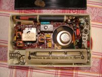
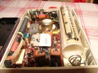
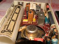
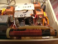
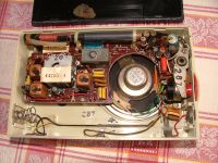
Portable radio with superheterodyne circuit using 7 germanium transistors: SFT317, SFT319, SFT319, SFT377, SFT353, SFT325, SFT377 and two germanium diodes: SFD110, SFD106. The radio receives Medium Waves, with the antenna wound on a ferrite core and the Intermediate Frequency (ZF/IF) at 455 kHz. The cabinet is made of plastic with the dial scale and the tuning knob on the front while the volume control and the power switch are on the left side. There is a headphone jack on the rear panel. The power supply can be supplied by 3 x 1.5V type C (LR14) batteries or via the mains (125÷240Vac) or from the car's 12Vdc system with the use of special adapters. The dimensions are: 6.5 x 4.1 x 1.6 inch (WxHxD). © IK3HIA 2007. |
|||
 |
 |
 |
 |
 |
 |
 |
 |
|
Radio portatile con circuito supereterodina che utilizza 7 transistor al germanio: SFT317, SFT319, SFT319, SFT377, SFT353, SFT325, SFT377 e due diodi al germanio: SFD110, SFD106. La radio riceve le Onde Medie, con l'antenna avvolta su un nucleo di ferrite. La Frequenza Intermedia (ZF/IF) è a 455 kHz. Il mobiletto in è plastica con la scala parlante e la manopola della sintonia sul frontale mentre il controllo del volume e l'interruttore di accensione sono sul lato sinistro. Nel pannello posteriore c'è la presa per l'auricolare. L'alimentazione può essere fornita da 3 x Batterie da 1,5 V tipo C (LR14) oppure tramite la rete elettrica (125÷240Vac) o dall'impianto a 12Vdc dell'auto con l'utilizzo di appositi adattatori. Le dimensioni sono: 16,8 x 10,5 x 4,5 cm (L,A,P). © IK3HIA 2007. |
|||
 |
 |
 |
 |
 |
|||
|
Return to top of
page
|
|||
|
|
Return to: IK3HIA home page |
|
Return to: Transistor Radio |
|
Go to: Transistor diagrams |