 |
GENERAL ELECTRIC mod. 676 |
 |
|
|
 |
Back to the description
Restoration |
|||
|
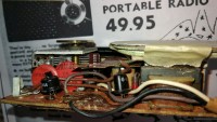
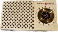
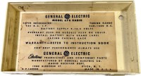
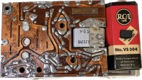
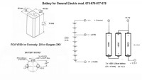
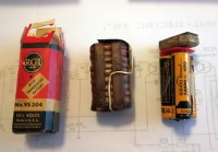
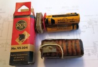
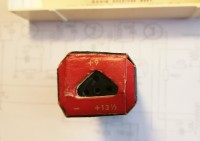
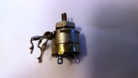
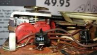
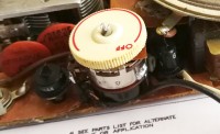
L'esemplare di G.E. 676 del quale sono venuto in possesso appariva in buone condizioni estetiche, era corredato della borsetta in cuoio, del suo auricolare e all'interno c'era addirittura l'introvabile batteria (ovviamente scarica) della RCA tipo VS304 con le due tensioni necessarie per il funzionamento. La prima operazione da me effettuata è stata quella di estrarre lo chassis della radio ed effettuare una minuziosa pulizia esterna ed interna del mobiletto, poi ho protetto con un disco ritagliato da un cartoncino la fragile membrana dell'altoparlante onde evitare di appoggiarci sopra inavvertitamente le dita e rovinarla. Una rapida misura con il tester dava ovviamente la vecchia batteria completamente esaurita, ma l'importante era avere a disposizione l'involucro e il relativo connettore tripolare per collegarla alla radio. Le tensioni necessarie per il funzionamento erano due: -13,5 e -4,5 Vcc, perciò ho subito provveduto a fare mente locale su quali batterie avrei potuto utilizzare per riprodurre i due voltaggi e quali avessero le dimensioni adatte per poter entrare nel contenitore originale che aveva dimensioni: 40x40x70 mm. Barando un po' e pensando che tutto sommato la radio doveva funzionare anche quando le batterie erano un po' scariche, ho provato a collegare in serie tre batterie stilo al litio tipo 14500. Queste batterie avevano le stesse dimensioni delle AAA, la tensione nominale per ciascuna era di 3,7 Volt e inoltre erano ricaricabili così avrei potuto riutilizzarle. Dopo aver ricaricato le 14500 con l'apposito caricabatterie Li-ion, le pile fornivano qualcosa di più di 4 Volt ciascuna. Poste in serie la tensione arrivava a 12 V e collegando una presa intermedia a un elemento avrei potuto prelevare i 4 V necessari per la polarizzazione del primo stadio di Frequenza Intermedia della radio. Dopo aver provveduto a estrarre dall'involucro il pacco originale di vecchie pile zinco-carbone, ho effettuato un po' di saldature tra le tre 14500 e il connettore tripolare e ho usato un po' di nastro adesivo trasparente per tenerle assieme. Il nuovo "pacco batterie" è entrato senza difficoltà nel vecchio contenitore di cartone della VS304 RCA (qui c'è lo schema di connessione delle pile). Il passo successivo è stato quello di dare un'occhiata allo schema elettrico della radio e sostituire il vecchio condensatore elettrolitico C2 da 20 MF (il C1 da 8 MF non era presente nel circuito). Per la sostituzione ho utilizzato un componente moderno che avesse lo stesso aspetto, la stessa capacità ma maggiore tensione di isolamento. Poi ho collegato la batteria e con un po' di trepidazione ho acceso la radio. Il risultato purtroppo è stato deludente: nessun segno di vita. Ho collegato il puntale positivo del tester a massa e il negativo sul collettore del transistor 2N44: azionando l'interruttore non ho misurato nessuna tensione. Dopo un rapido controllo ho appurato che il doppio interruttore coassiale al potenziometro del volume non funzionava, entrambi i contatti erano isolati. Mi sono rimboccato le maniche e mi sono imbarcato nella difficile impresa di dissaldare il potenziometro con l'intento di aprirlo e pulirne i contatti interni. E' stato un lavoro lavoro piuttosto arduo, anche perché l'oggetto era fragile e con il calore del saldatore le piste del vecchio circuito stampato avevano la tendenza a sollevarsi e a staccarsi dal materiale isolante. Quando finalmente ho avuto tra le mani il potenziometro ho dovuto purtroppo constatare che sforzandolo per estrarlo dalla sede avevo interrotto la sottile striscia resistiva interna. In preda all'avvilimento mi sono chiesto: dove avrei mai potuto rintracciare un potenziometro simile? La resistenza era di 5 kOhm e il perno era da 3 mm mentre quelli in vendita nei negozi di elettronica avevano tutti l'asse da 6 mm e poi nessuno era dotato di interruttore doppio. Ancora una volta ho trovato la salvezza nel mio magico cassetto delle meraviglie. Rovistando tra il ciarpame accumulato negli anni, nascosto tra vecchi zoccoli di valvole, resistenze a filo, vetuste bobine di MF e tanti vecchi potenziometri ho trovato qualcosa che avrei potuto utilizzare per riparare al mio errore. Le dimensioni del piccolo potenziometro rinvenuto nel cassetto erano leggermente maggiori di quelle dell'originale e inoltre il perno aveva il diametro di 4 mm, ma la resistenza era di 5 kOhm e aveva doppio interruttore, perciò con un po' di lavoro forse avrei potuto adattarlo. In realtà c'è voluto un intero giorno di duro lavoro, ma usando a lungo la lima per ridurre il diametro dell'asse e piegando e prolungando i contatti degli interruttori con degli spezzoni di filo di rame, con tanta pazienza sono riuscito ad adattare il ricambio e farlo entrare nello spazio precedentemente occupato dal vecchio potenziometro. Questa volta dopo aver acceso la radio la tensione misurata sul collettore del 2N44 era di -12 V e alzando il volume dall'altoparlante proveniva un fruscio rassicurante. Ruotando con impazienza la manopola della sintonia ho subito rintracciato l'emittente privata in Onde Medie che nella mia zona trasmette a 1017 kHz e con il potenziometro del volume al massimo il suono era abbastanza forte. Tenendo conto che la potenza massima a disposizione era di 60 mW l'intensità sonora era di tutto rispetto. Dopo sessantotto anni i transistor e gli altri componenti della vecchia la General Electric funzionavano ancora, segno tangibile della bontà del progetto e dei materiali usati a metà degli anni 50. Preso dall'entusiasmo ho registrato un breve video per immortalare il momento. Per scrupolo ho effettuato l'allineamento dei trasformatori di media frequenza con il mio fidato oscillatore Heatkit SG8 regolato a 455 kHz senza notare però miglioramenti sensibili, segno che le bobine della radio non erano fuori allineamento. Poi ho rimontato lo chassis della radio nel mobiletto e ho registrato un altro corto video per certificare la conclusione del restauro. © IK3HIA, 2024. |
|||||
|
|
|||||
 |
 |
 |
 |
||
 |
 |
 |
 |
||
 |
 |
 |
 |
||
|
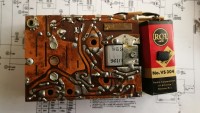
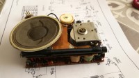
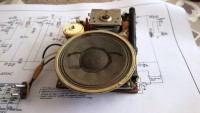
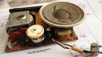
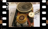
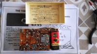
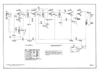
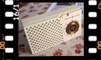
The GE 676 specimen I purchased appeared in good aesthetic condition, it was accompanied by the original leather bag with the strap to hang on the shoulder, its earphone and inside the radio even had the unobtainable RCA type battery (obviously flat) VS304 with the two voltages necessary to make it work. The first operation I carried out was to extract the chassis of the radio and carry out a thorough cleaning of the cabinet, then I protected the fragile membrane of the speaker with a cardboard disc to avoid inadvertently placing my fingers on it and ruining it. A quick measurement with the tester obviously showed the old battery to be completely discharged, but the important thing was to have available the casing and the relevant three-pole connector that connected it to the radio. There were two voltages necessary for operation: -13.5 and -4.5 Vdc, so I immediately thought about which batteries I could use to reproduce the two voltages and which batteries could have fit into the casing which had dimensions: 1.5748 x 1.5748 x 2.7559 inches. Cheating a little and thinking that all in all the radio should work even when the batteries were a little flat, I tried putting three 14500 type lithium batteries in series. These batteries had the same dimensions as an AAA, the nominal voltage for each was 3.7 Volts and also they were rechargeable so I could reuse them. After recharging the 14500 with the appropriate Li-ion charger, the batteries gave something more than 4 Volts each. Placed in series they provided 12 V and by connecting an intermediate socket to an element I could draw the 4 V necessary for the polarization of the first Intermediate Frequency stage of the radio. After having done a bit of soldering between the elements and the three-pole connector, and using a bit of adhesive tape to hold it together. The new "battery pack" fit easily into the old cardboard container of the VS304 RCA (here is the battery connection diagram). The next step was to take a look at the radio wiring diagram and replace the old 20 MF C2 electrolytic capacitor (the 8MF C1 was not present in the circuit) with a modern component that had the same appearance, same capacitance and higher isolation voltage, then I connected the battery and with some trepidation I turned on the radio. Unfortunately, the result was disappointing: no sign of life. I connected the positive tip of the tester to ground and the negative to the collector of the 2N44 transistor: when the switch was activated, no voltage arrived. After a quick check I found that the double coaxial switch on the volume potentiometer was not working, both contacts were isolated. I rolled up my sleeves and I set about the task of desoldering the potentiometer with the intention of opening it and cleaning its internal contacts. It was a rather difficult job, also because the object was fragile and with the heat of the soldering iron the tracks of the old printed circuit had a tendency to lift and detach from the insulating material. When I finally had the potentiometer in my hands I unfortunately had to realize that by forcing to extract it from its seat I had broken the thin internal resistive strip. Full of dejection I asked myself: where could I ever find such a potentiometer? The resistance was 5 kOhm and the pin was 0.118 in, while all those on sale in electronics stores had a 0.2362 in pin and then none were equipped with a double switch. Once again I found salvation in my magical drawer of wonders. Rummaging through the junk accumulated over the years, hidden among old valve sockets, old wire resistors, old MF coils and many old potentiometers I found something that I could use to repair my mistake. The dimensions of the small potentiometer found in the drawer were slightly larger than those of the original and the pin had a diameter of 0.1574 in, but the resistance was 5 kOhm and it had double switches, so with a little work I could have adapted it. It actually took a whole day of hard work, but using the file to reduce the diameter of the axis and bending and extending the switch contacts with short copper wires, with a lot of patience I managed to adapt the replacement and make it fit into the space occupied by the old potentiometer. This time after turning on the radio the voltage measured on the collector of the 2N44 was -12 V and when the volume was raised a reassuring hiss came from the speaker. Impatiently I turned the tuning knob and immediately I found the private Medium Wave radio station that broadcasts at 1017 kHz in my area, and with the volume pot at maximum the sound was quite loud. Taking into account that the maximum power available was 60 mW, the sound intensity was very respectable. After sixty-eight years, the transistors and other components of the old General Electric was still working good, a tangible sign of the quality of the design and the materials used in the mid-1950s. Taken by enthusiasm, I recorded a short video to immortalize the moment. To be careful, I aligned the Intermediate Frequency transformers with my trusty Heatkit SG8 oscillator set at 455 kHz but without noticing any significant improvements, a sign that the radio coils were not out of alignment. Then I reassembled the radio chassis in the cabinet and recorded another short video to certify the completion of the restoration. © IK3HIA, 2024. |
|||||
 |
 |
 |
 |
||
 |
 |
 |
 |
||
|
Back to the 676 description page |
|||||
|
|
Return to: IK3HIA home page |
|
Return to: Transistor Radio |
|
Go to: Transistor diagrams |