 |
COMMUNICATION ELECTRONICS INC. TYPE 907 USA (1965) |
|
|
|
COMMUNICATION ELECTRONICS INC. TYPE 907 USA (1965) |
|
|
|
|||||
|
|
Description Restoration Data sheet |
 |
Descrizione Restauro Scheda tecnica |
|
|
|
|
|||||
 |
 |
 |
 |
||
 |
 |
 |
 |
||
 COMMUNICATION
ELECTRONICS INC. TYPE 907 Rockville - Maryland - USA - The Type
907 receiver was created and marketed by the CEI company in 1965. CEI
was subsequently purchased by the Watkins-Johnson company in 1967. COMMUNICATION
ELECTRONICS INC. TYPE 907 Rockville - Maryland - USA - The Type
907 receiver was created and marketed by the CEI company in 1965. CEI
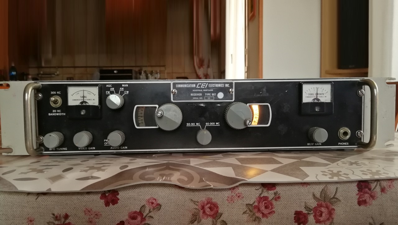
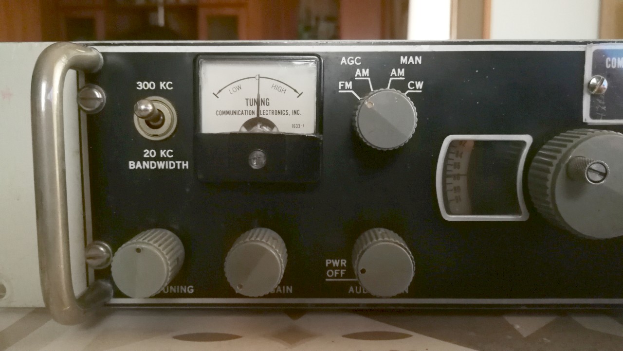
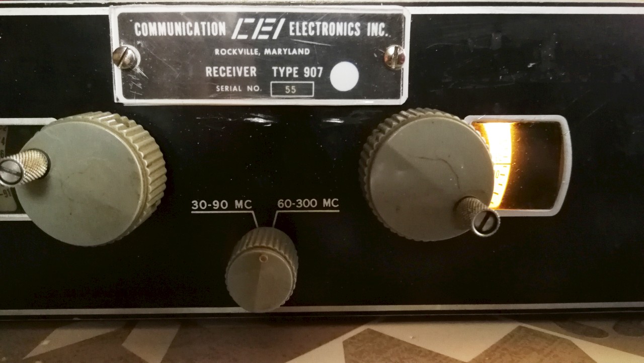
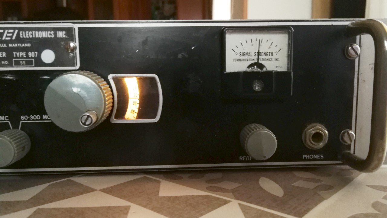
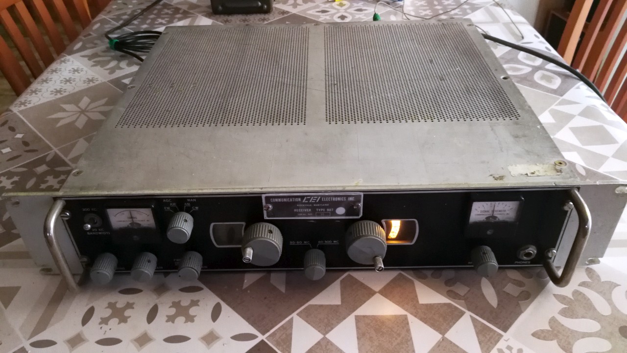
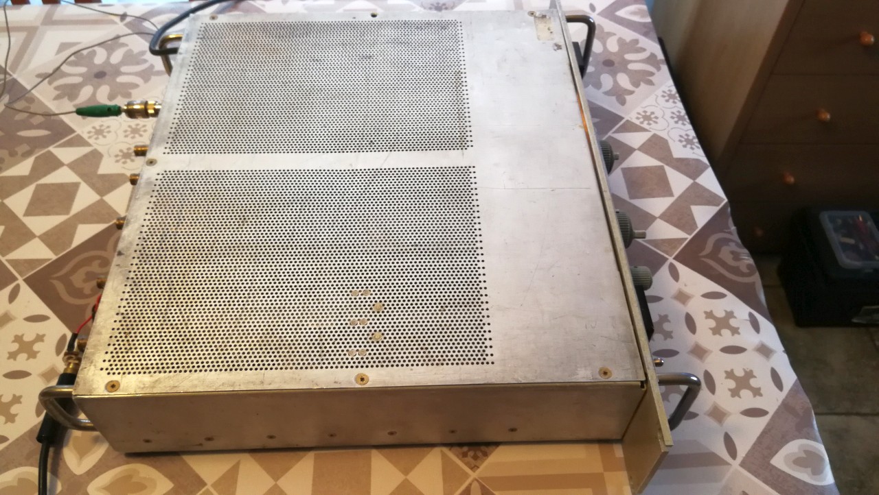
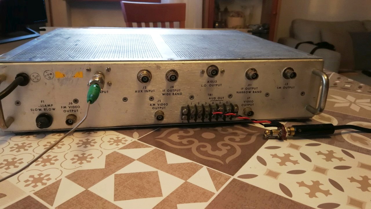
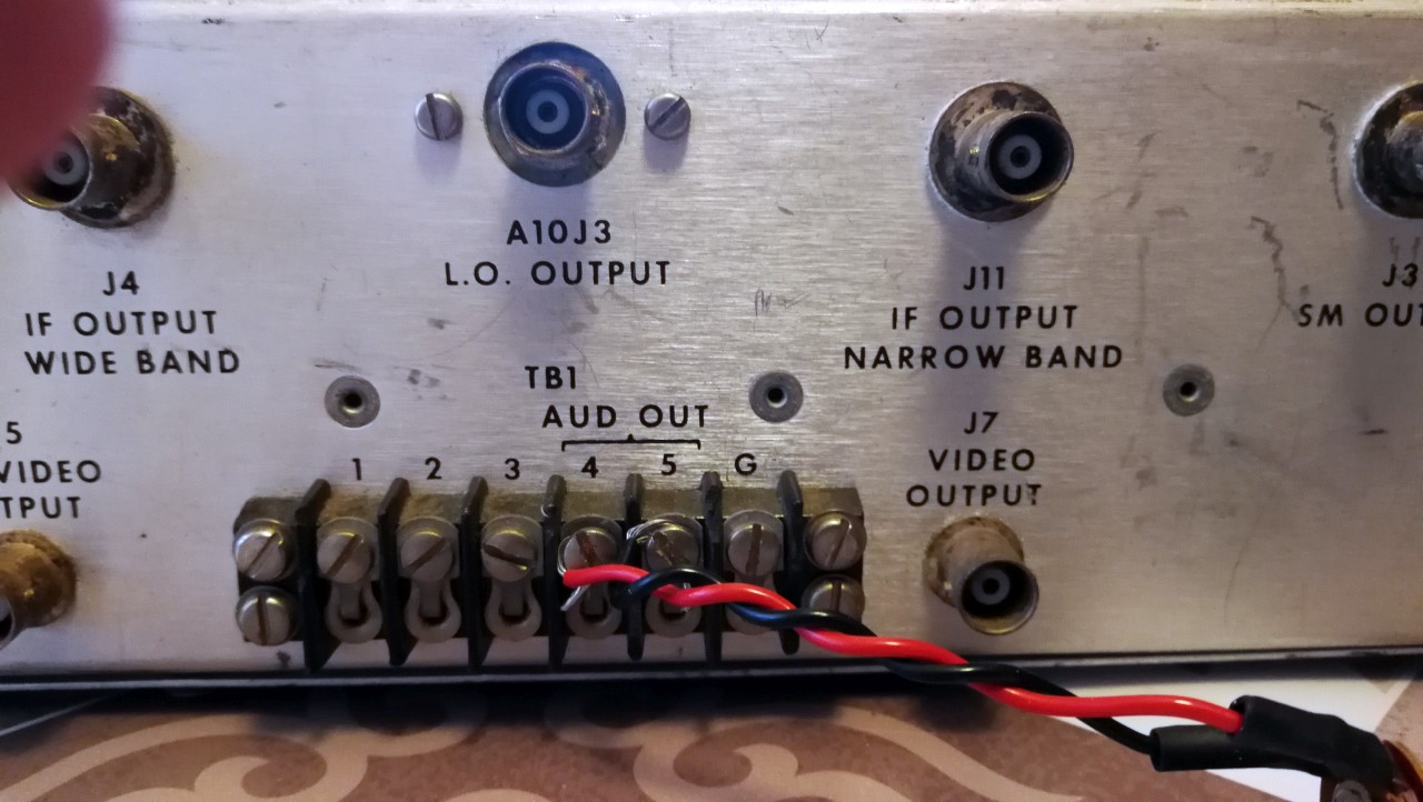
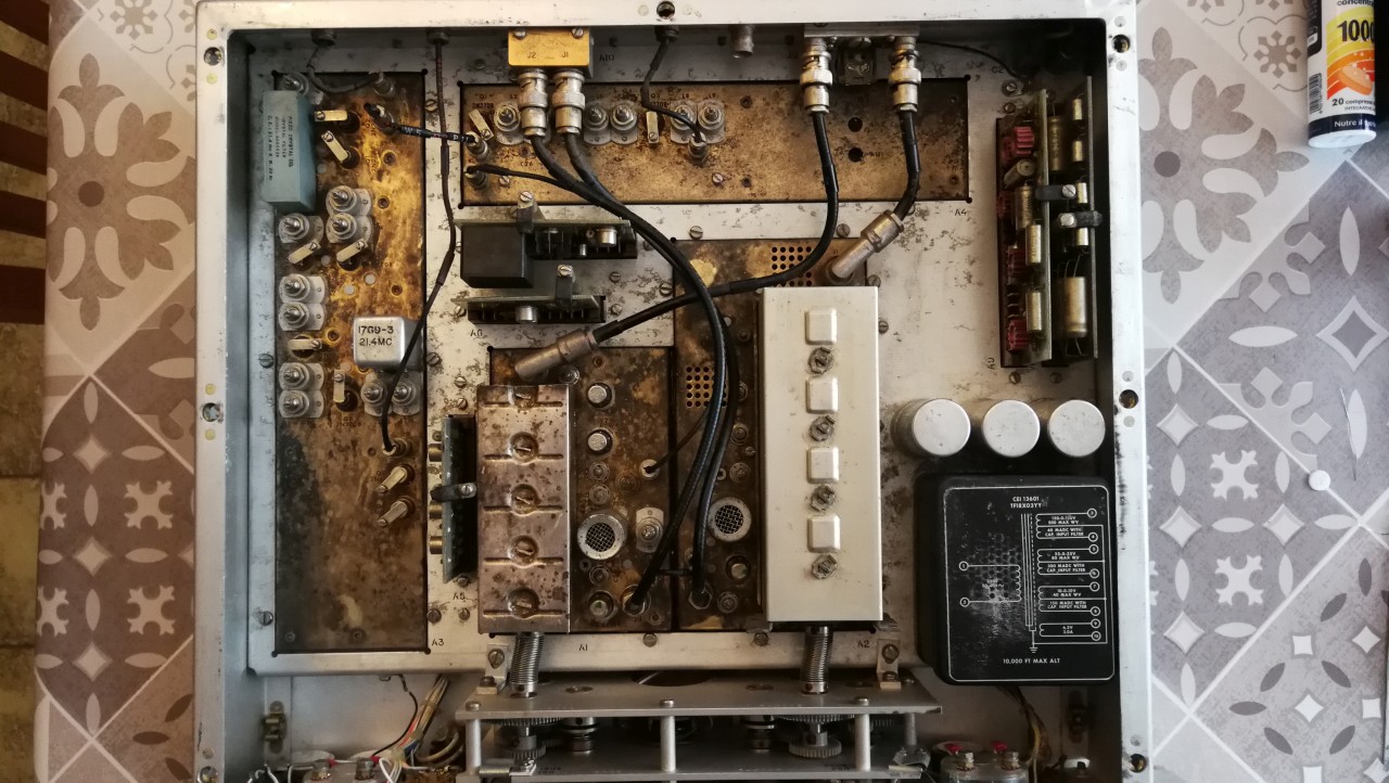
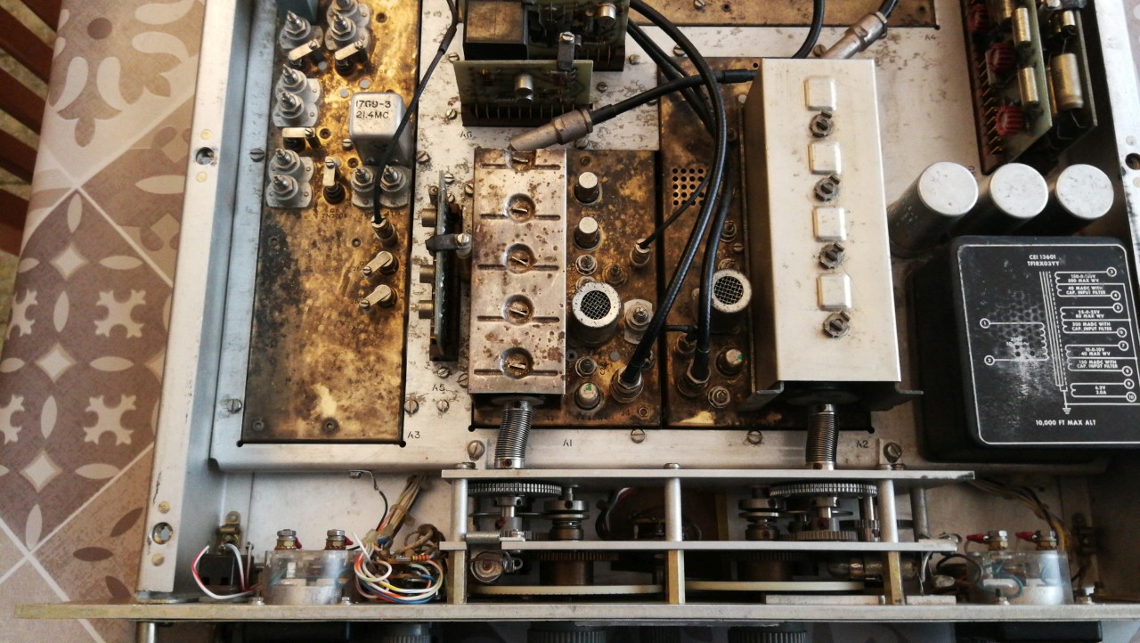
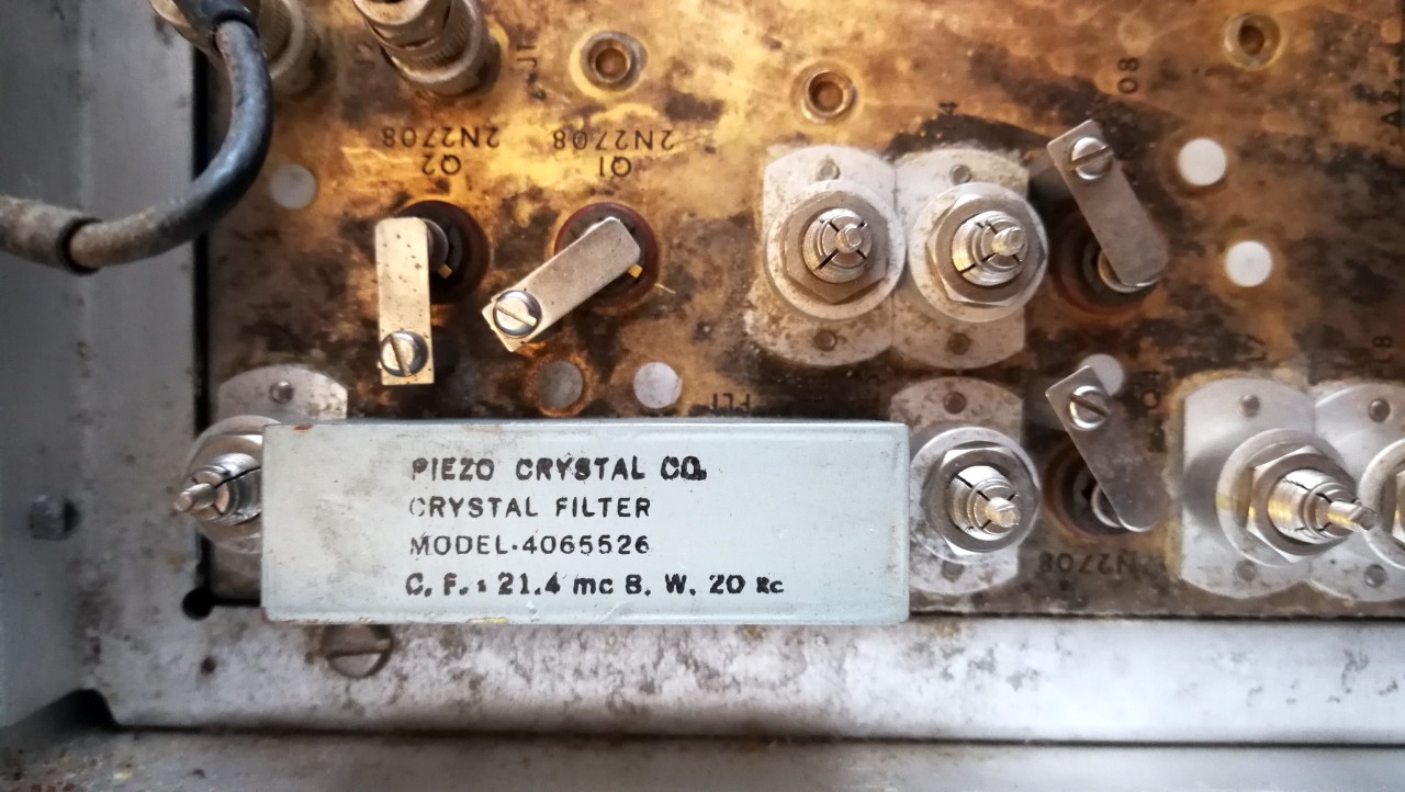
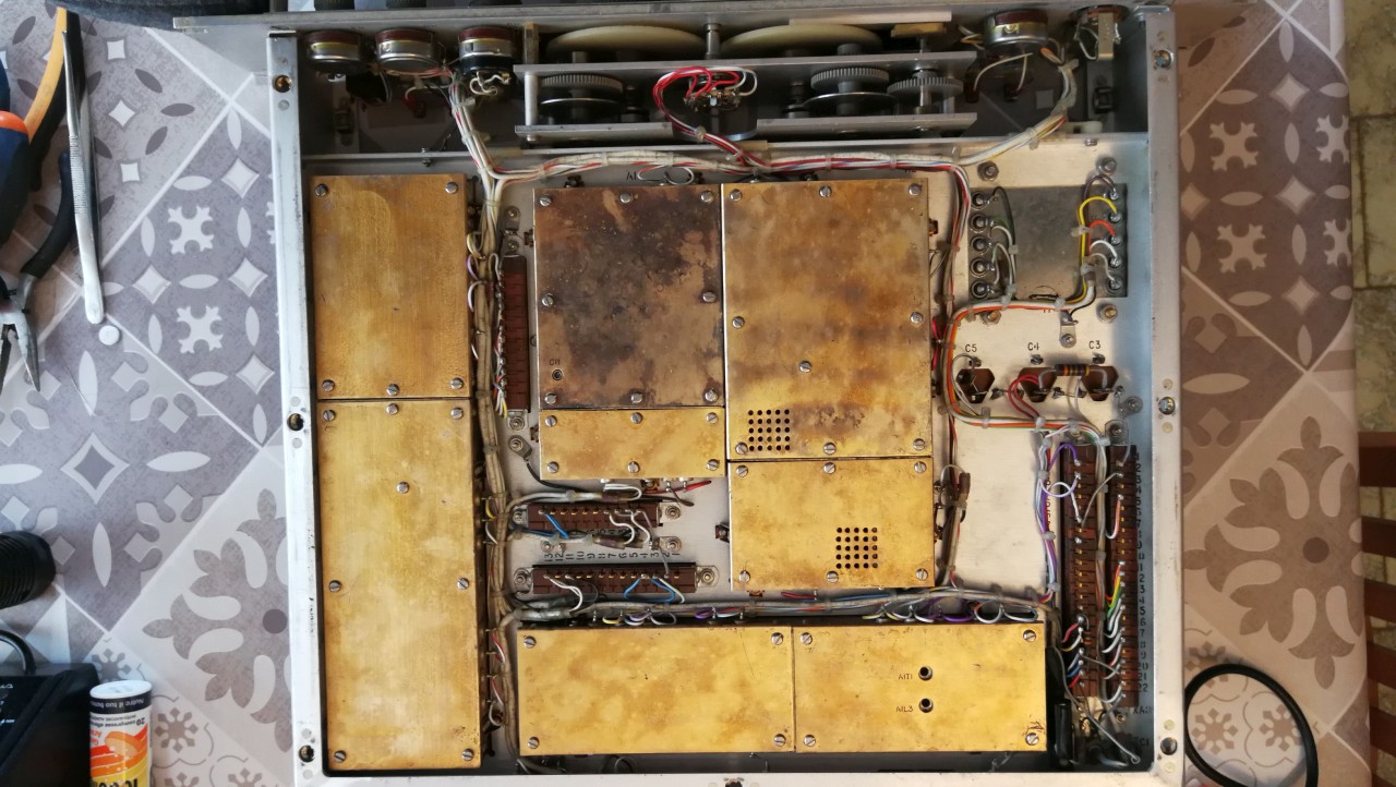
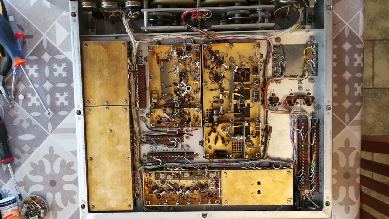
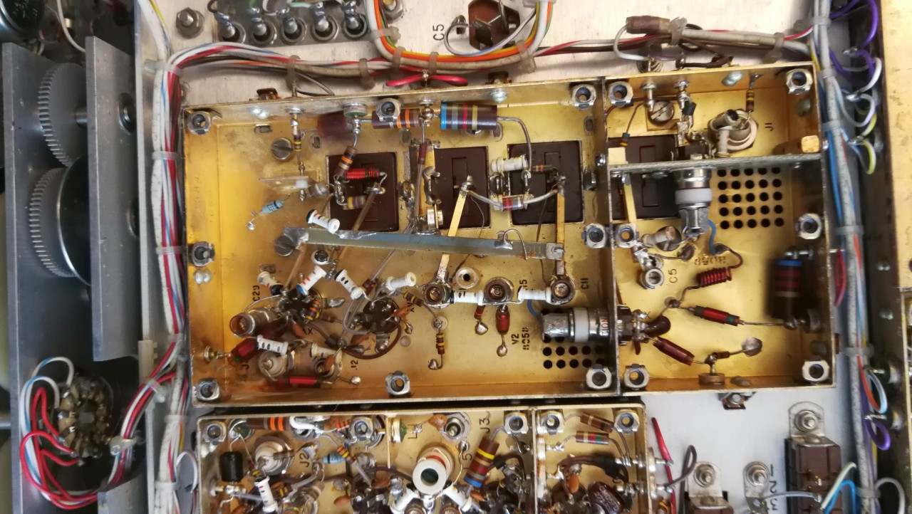
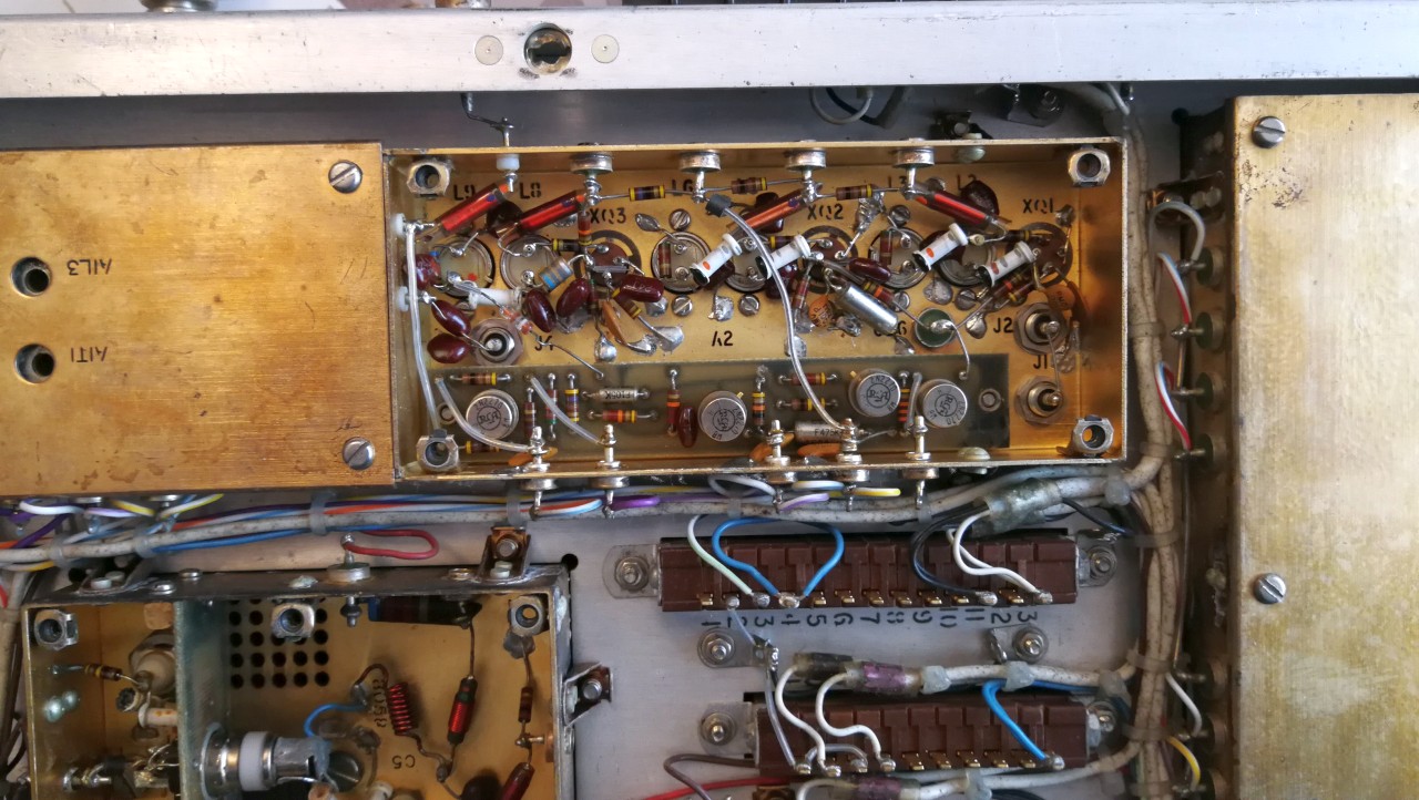
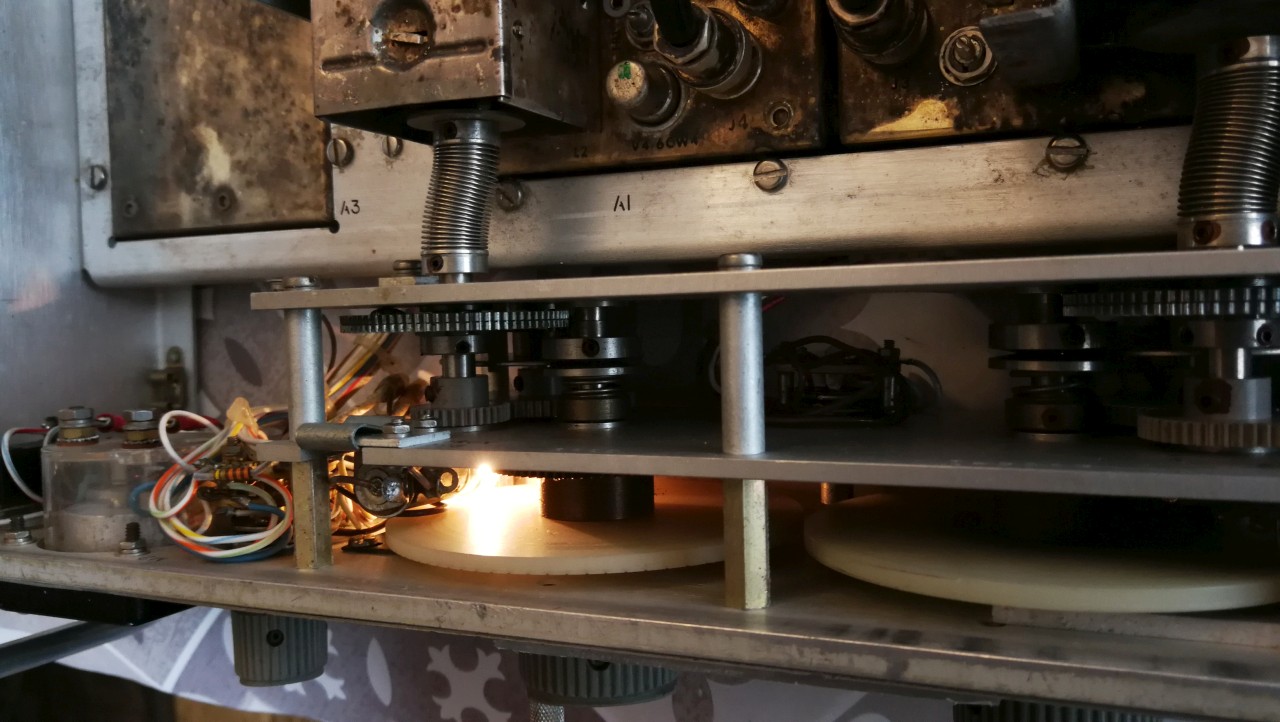
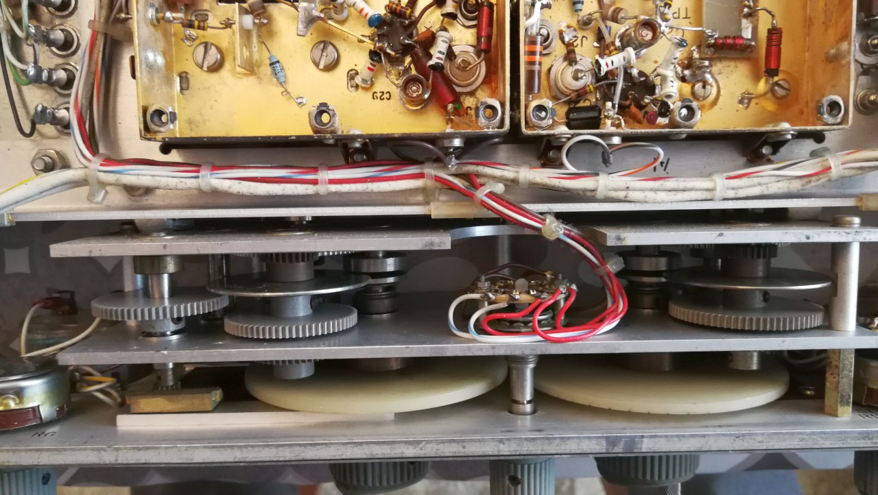
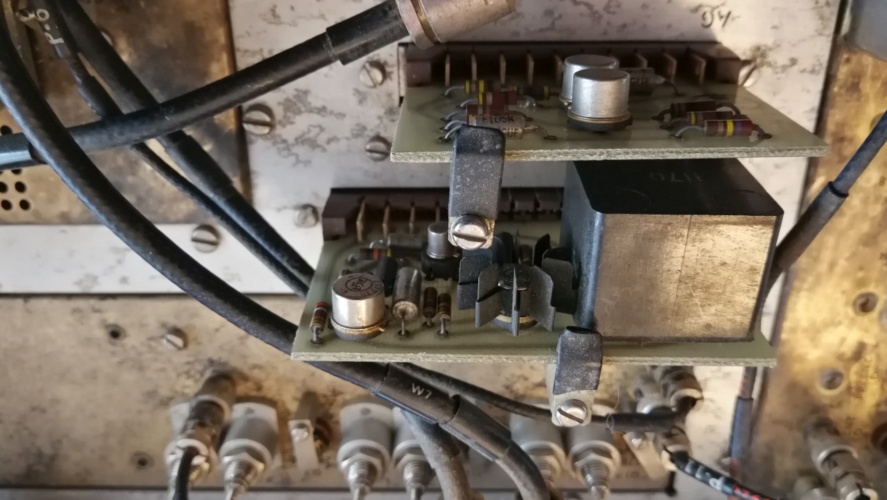
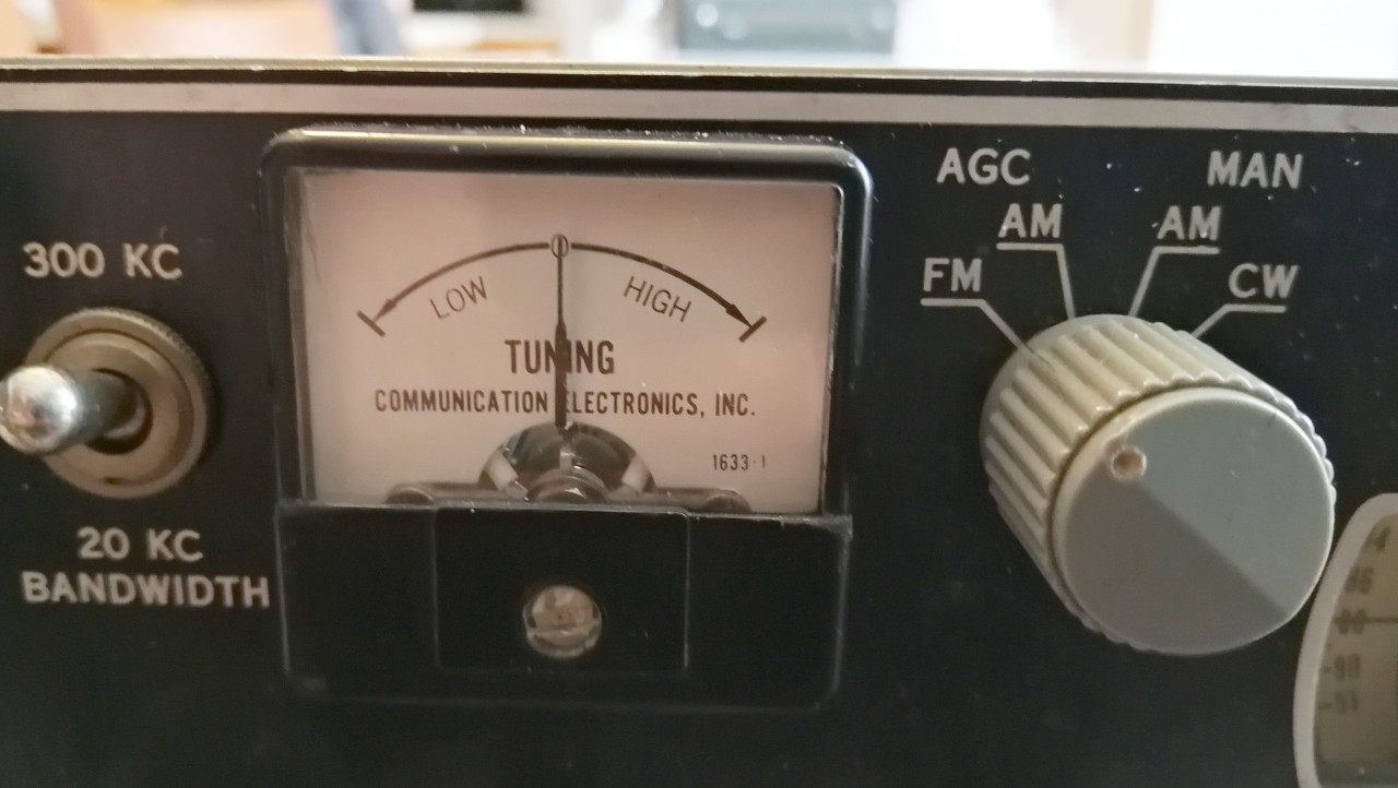
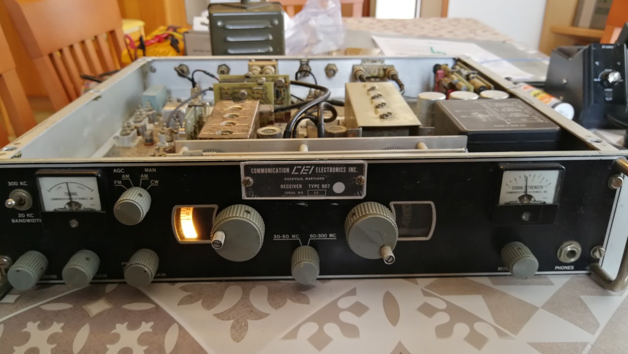
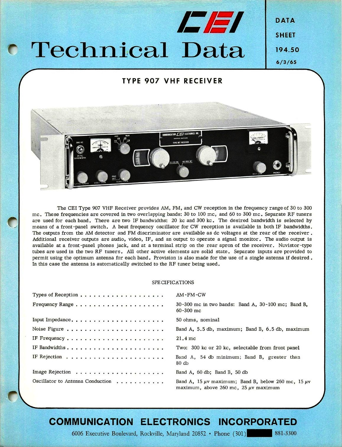
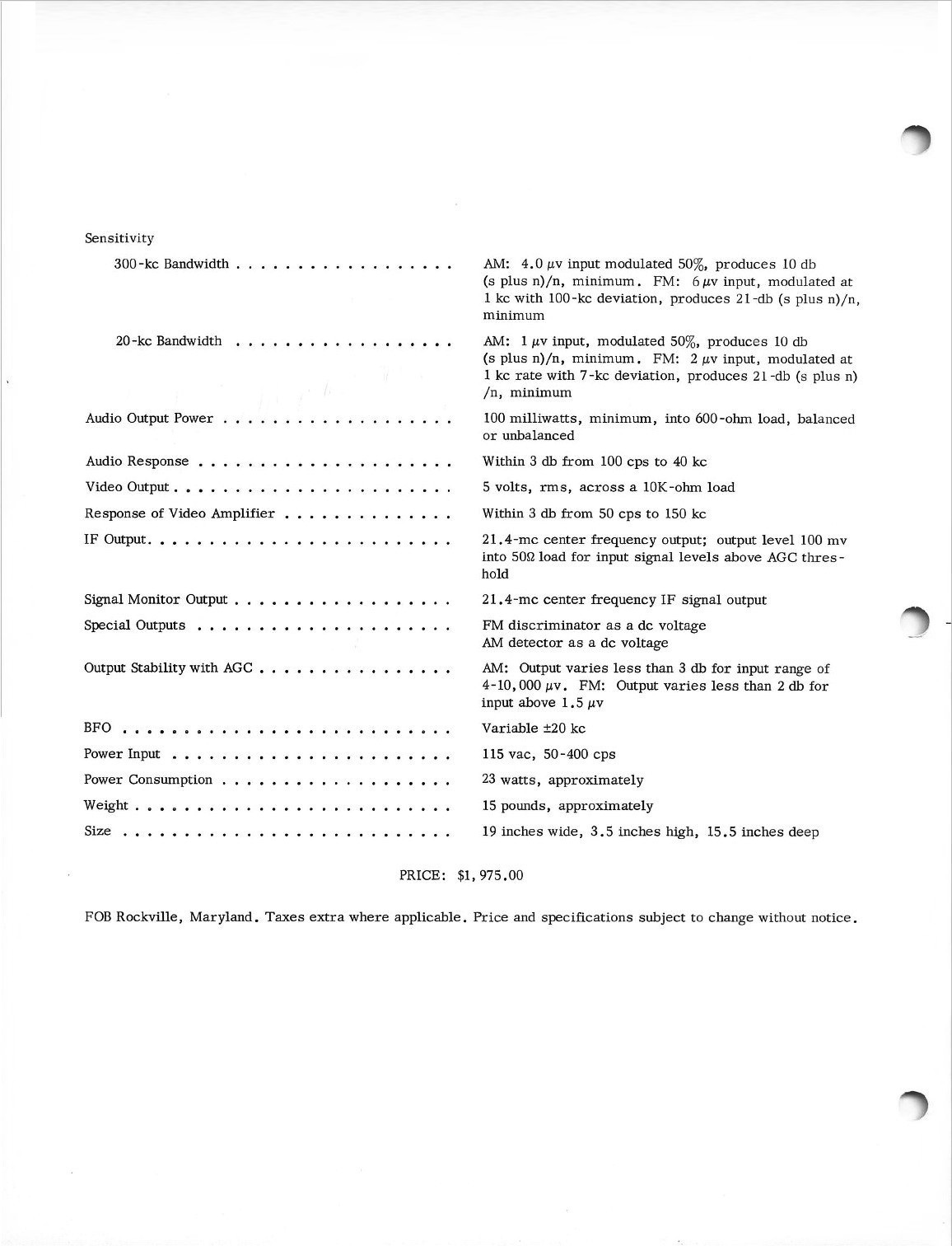
was subsequently purchased by the Watkins-Johnson company in 1967.The input circuits of the two frequency ranges were separate and were made using nuvistor valves. In those years, silicon transistors were already on the market, but the performance at high frequencies of semiconductors was not yet comparable to that of the nuvistor valves which had closed the era of vacuum tubes in style. The front end of the 30-90 MHz range (circuit A1) used three 6CW4 triodes and one 7587 tetrode. The 60-300 MHz range circuit (A2) instead used two 8058 triodes, one 7587 tetrode and one 6CW4 triode. The Type 907 receiver was made with hybrid technology because as active elements it also took advantage of the new technologies that were increasingly spreading at the time and apart from the two front ends, the rest of the radio circuits were made with semiconductors. For the eight nuvistor valves used, 55 silicon transistors were used divided into the various circuits. In the chassis of the intermediate frequency (circuit A3) which resonated at 21.4 MHz and was equipped with a crystal filter from the Piezo Crystal Co., 6 2N2708 and two 2N697 silicon transistors were used, mounted on a socket in the upper part, while 2 x 2N697 and four 2N706 were mounted underneath the brass chassis. The A2 circuit that amplified the Video signals was made with three 2N2708 transistors mounted on a socket above the chassis and 4 x 2N2270 in the lower part. Next to the A2 there was the A4 chassis, also a video amplifier, which used three 2N2270 and four 2N706 in the lower part. The receiver also used transistors in the various accessory circuits and in the audio amplifier. The A5 circuit used one 2N1131 and two 2N697 while the A6 was made with one 2N697 and one 2N1131. The Low Frequency circuit in the A7 circuit employed one 2N929 and two 2N2270 which provided an output of 100 mW with bandwidth from 100 Hz to 40 Khz into a load of 600 Ohm. The power supply part used two 2N1030 and three 2N2270 in the A8 regulation circuit while the A9 contained the silicon rectifier diodes for the various voltages used by the receiver and used two 1N3255 and ten 1N3253. The power transformer had a 115 Vac input (220 Vac for the examples marketed in Europe) and the following outputs: 150 + 150 Vac 40 mA for the anode voltage, 25 + 25 Vac 80 mA, 10 + 10 Vac 40 mA and 6.3 Vac 2 A for the valve filaments and for the 2 incandescent bulbs that illuminated the two speaking scales with mechanical gear reduction. The aluminum front panel was equipped with steel handles and from left to right the following controls were located: BFO Tuning, knob for fine tuning the CW continuous wave signals, the 300/20 Kc Bandwidth selector, the Video Gain, the device was turned on with the volume control (Power On and Audio Gain). Further to the right there was an FM, AM and CW switch, a milliammeter with a central zero for precise signal tuning. In the center of the front there was the switch that selected the two VHF reception bands, from 30 to 90 and 60 to 300 MHz, with the respective scaled-down tuning knobs on the side. On the right was the RF/IF gain control knob, the milliammeter indicating the RF signal strength, and the jack connector with the headphone output. The radio had two inputs and many outputs. On the rear panel, also equipped with steel handles, from left to right there was the power cable, the 0.15 A F1 fuse holder, the BNC connector (J6) for FM Video Output, the BNC connectors ( J1) antenna input and the auxiliary input (J2), the AM Video output (J5), the IF Output Wideband - Broadband Intermediate Frequency Output (J4), L.O. Output (A10J3), the TB1 terminal block with the 600 Ohm audio output to be connected to contacts 4 and 5. Further to the right were the IF Output Narrow Band (J11), the BNC Video Output (J7) and the S.M. Outputs (J3). The CEI Type 907 was a robust radio, built for professional and continuous use with the mixed technique used in the early 1960s. The power and audio frequency circuits were made on printed circuit boards inserted vertically into multi-contact connectors. The radio frequency parts, however, were made on some brass chassis with the active elements such as valves and transistors mounted on sockets and passive components and other transistors connected in the compartment below, then closed with a brass cover and fixed with screws. The tuning took place via two gear ratios that moved complicated variable inductances with worm screws. Connections between one circuit and another were made via RF connectors and coaxial cables. The various power supply voltages and audio signals were distributed between the power supply and the various chassis via insulated copper wires and shielded cables. The dimensions of the receiver were: 19 x 3.5 x 15.5 inches (W,H,D) and the weight was about 15 pounds. The price in 1965 was $1,975.00. IK3HIA © 2023 |
|||||
 |
 |
 |
 |
||
 |
 |
 |
 |
||
|
Back to the top of the page >>
|
|||||
|
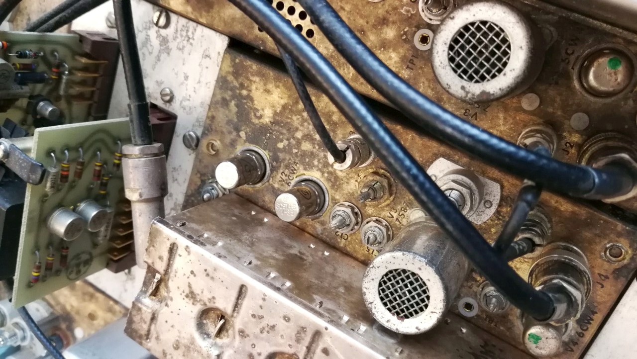
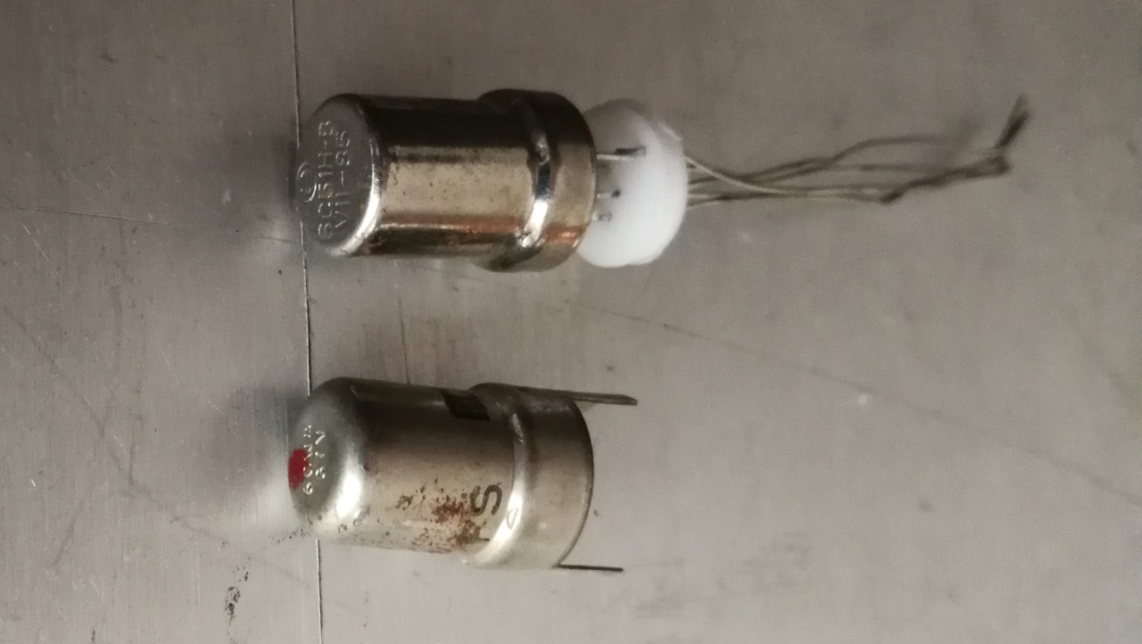
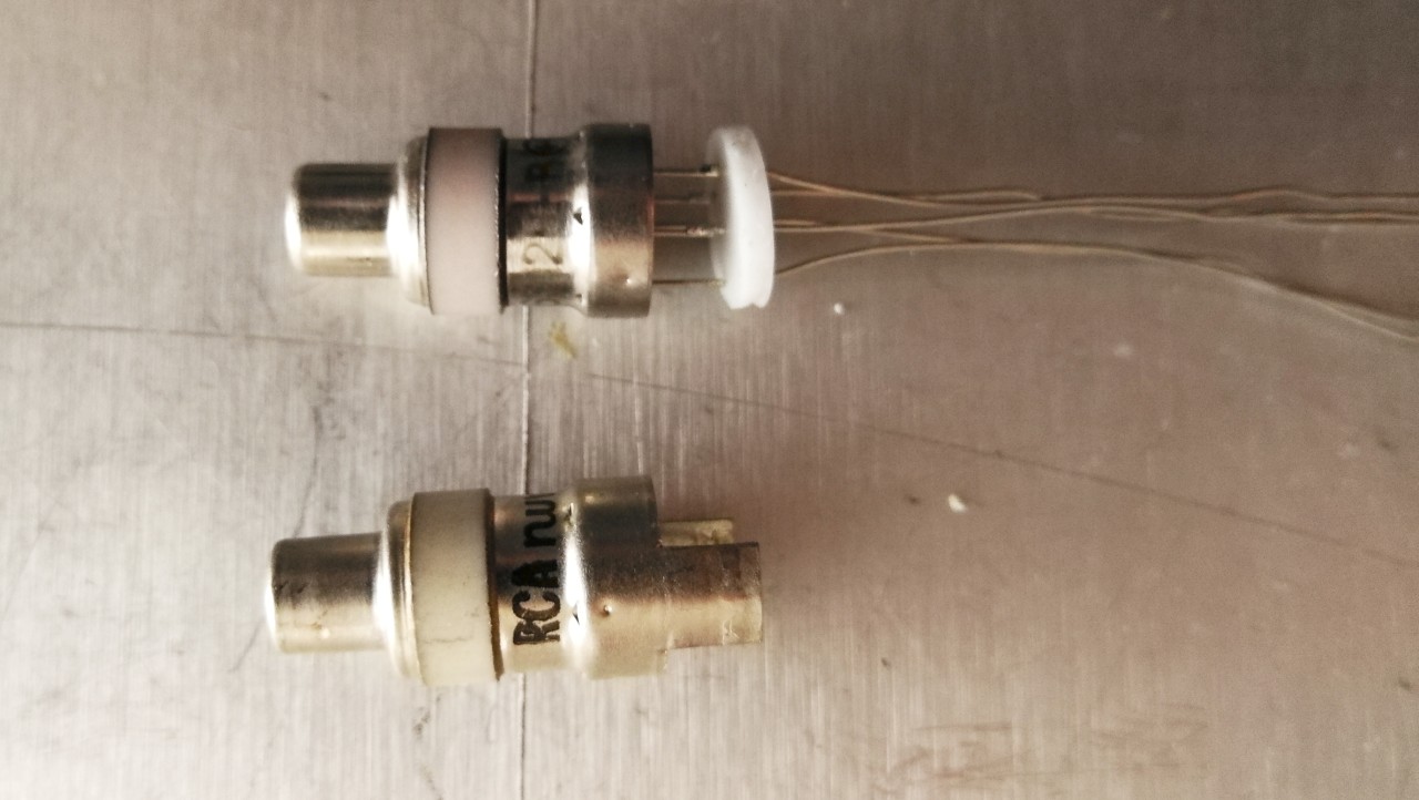
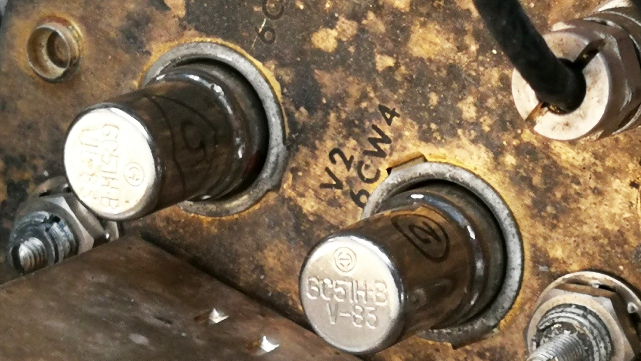
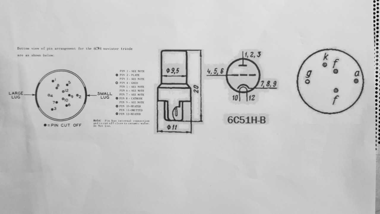
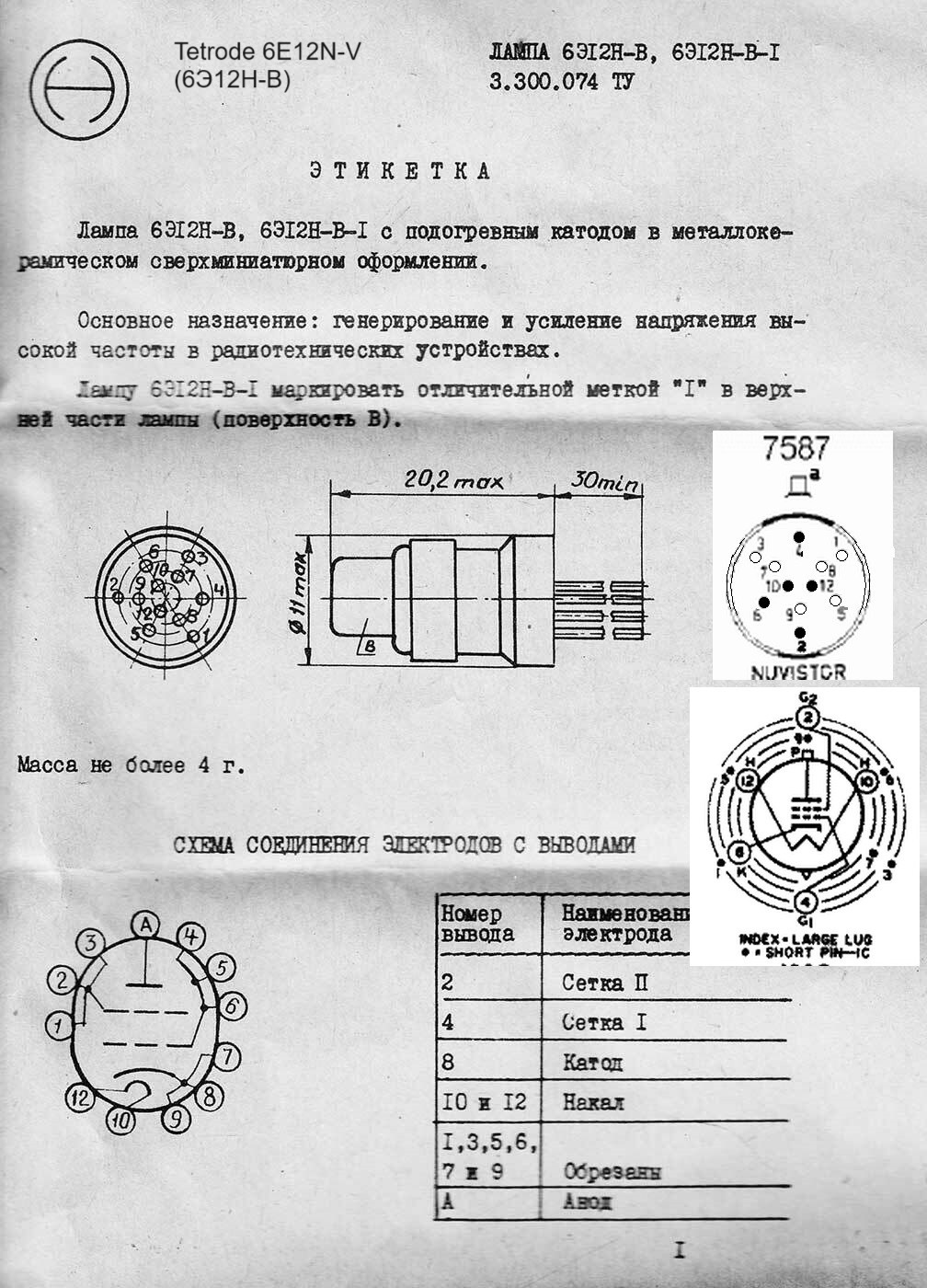
Restoration To the example in my possession I immediately connected a military surplus LS-166 type speaker which has an 8-600 Ohm switch and a simple copper wire used as antenna and I inserted the mains cable into the socket. The radio turned on but its two dial scale lamps were burnt out and the A band, the one that ranged from 30-90 MHz, was completely silent. The other band, the B from 60-300 MHZ, worked perfectly and with the bandwidth selector set at 300 Kc it allowed me to listen to some FM broadcasting stations, and by selecting the 20 Kc bandwidth I also listened to the control towers of nearby airports with a strong signal in AM from 115 MHz and above. Replacing the 6.3V bulbs was not difficult while to repair the A band I had to do many attempts, first exchanging the electronic tubes with the working VHF band circuit and then measuring voltages and components with the tester. I was eventually disappointed to discover that three of the tuner A nuvistor tubes had good filaments but were actually out of order. Two 6CW4s had their plates shorted to the grid while the 7587 was completely burned out. The nuvistor 6CW4 valves are still available in the market online but in Europe have prices ranging from € 20 to 90 each plus shipping. The 7587 is cheaper, but the price varies from € 10 to 70 plus shipping. Looking for an alternative, I first wasted some time trying to replace the 6CW4 triodes with 2N2222 transistors by inserting resistors of a few tens of kOhm between the collector and the anode circuit. Fortunately I didn't cause any explosions or smoke but the result was negative and furthermore the operation definitely went against the ethics of a good restorer. Then I remembered that while I was looking for nuvistor valves online, on the well-known online auction site I had noticed some nuvistors with strange acronyms produced in the former USSR and that these valves were offered at much more affordable prices than the original RCA or Philips ones. To make a long story short, I ordered some Soviet nuvistors from a Kiev seller with which I would try to carry out the repair. With a 6E12N-V (6Э12ЭН-В) tetrode I would have tried to replace the faulty 7587 and with two 6C51H-B triodes I would have tried to replace the 6CW4's. The wait wasn't very long, and despite the ongoing war, after a fortnight I received a well-packaged small box from Kiev with the ordered material inside. The Russian nuvistors were new and unlike the RCA ones they had elongated pins with silver copper wires, but by cutting the excess with the cutters and checking on the datasheets that the pinout were the same, I inserted the tubes in the right direction and with determination into the USA valve sockets. After a moment of hesitation, I selected the 30-90 MHz frequency band, turned on the receiver and waited with trepidation for the tube filaments to heat up. With relief and extreme joy the loud FM hiss came out of the LS-166 and by turning the knob I was able to tune in various commercial stations from 87 to 90 MHz. The old CEI Type 907 receiver was now working properly again in both VHF ranges. IK3HIA©2023 |
|||||
 |
 |
 |
 |
||
 COMMUNICATION ELECTRONICS INC. TYPE 907 Rockville
- Maryland - USA - Il ricevitore Type 907 fu realizzato e
commercializzato dalla ditta CEI dal 1965. La CEI fu successivamente
acquistata dalla società Watkins-Johnson nel 1967.
COMMUNICATION ELECTRONICS INC. TYPE 907 Rockville
- Maryland - USA - Il ricevitore Type 907 fu realizzato e
commercializzato dalla ditta CEI dal 1965. La CEI fu successivamente
acquistata dalla società Watkins-Johnson nel 1967.La radio era studiata appositamente per il monitoraggio audio e video dei segnali radio VHF nei modi di ricezione AM, FM e CW e copriva lo spettro di frequenze da 30 a 300 MHz in due gamme, rispettivamente da 30 a 90 MHz e da 60 a 300 MHz. La banda passante della frequenza intermedia poteva essere di 20 KHz oppure di 300 KHz. I circuiti d'ingresso delle due gamme di frequenza erano separati e erano realizzati con l'utilizzo di valvole nuvistor. In quegli anni erano già in commercio i transistor al silicio, ma le prestazioni alle frequenze elevate dei semiconduttori non erano ancora paragonabili a quelle delle valvole nuvistor che avevano chiuso in bellezza l'epoca dei tubi a vuoto. Il front-end della gamma 30-90 MHz (circuito A1) utilizzava tre triodi 6CW4 e un tetrodo 7587. Il circuito della gamma 60-300 MHz (A2) impiegava invece due triodi 8058, un tetrodo 7587 e un triodo 6CW4. Il ricevitore Type 907 era realizzato con tecnologia ibrida perché come elementi attivi usufruiva anche delle nuove tecnologie che all'epoca stavano sempre più diffondendosi e a parte i due front end, il resto dei circuiti della radio era realizzato con semiconduttori. A fronte delle otto valvole nuvistor utilizzate venivano utilizzati ben 55 transistor al silicio suddivisi nei vari circuiti. Nello chassis della frequenza intermedia (circuito A3) che risuonava a 21,4 MHz e che era dotata di un filtro a cristallo della Piezo Crystal Co. venivano impiegati 6 transistor al silicio 2N2708 e due 2N697 montati su zoccolo nella parte superiore, mentre nella parte sottostante dello chassis di ottone erano montati 2 x 2N697 e quattro 2N706. Il circuito A2 che amplificava i segnali Video era realizzato con tre transistor 2N2708 montati su zoccolo sopra lo chassis e 4 x 2N2270 nella parte inferiore. A lato dell'A2 c'era lo chassis A4 sempre amplificatore video che utilizzava nella parte inferiore tre 2N2270 e quattro 2N706. Il ricevitore utilizzava transistor anche nei vari circuiti accessori e nell'amplificatore audio. Il circuito A5 impiegava un 2N1131 e due 2N697 mentre l'A6 era realizzato con un 2N697 e un 2N1131. La Bassa Frequenza impiegava nel circuito A7 un 2N929 e due 2N2270 che fornivano un'uscita di 100 mW con banda passante da 100 Hz a 40 Khz su un carico di 600 Ohm. La parte di alimentazione impiegava nel circuito di regolazione A8 due 2N1030 e tre 2N2270 mentre l'A9 conteneva i diodi raddrizzatori al silicio per le varie tensioni utilizzate dal ricevitore e impiegava due 1N3255 e dieci 1N3253. Il trasformatore di alimentazione aveva l'ingresso a 115 Vac (o a 220 Vac per gli esemplari commercializzati in Europa) e le seguenti uscite: 150 + 150 Vac 40 mA per la tensione anodica, 25 + 25 Vac 80 mA, 10 + 10 Vac 40 mA e 6,3 Vac 2 A per i filamenti delle valvole e per le lampadine a incandescenza che illuminavano le due scale parlanti a demoltiplica meccanica. Il pannello frontale di alluminio era dotato di maniglie d'acciaio e da sinistra a destra erano collocati i seguenti controlli: BFO Tuning, manopola per la sintonia fine dei segnali a onda continua CW, il selettore della banda passante 300/20 KHz Bandwidth, il Video Gain, l'accensione dell'apparecchio avveniva con il comando del volume (Power On e Audio Gain). Più verso destra c'era commutatore FM, AM e CW, un milliamperometro con zero centrale per la precisa sintonia del segnale. Al centro del frontale era collocato il commutatore che selezionava le due bande di ricezione VHF, da 30 a 90 e 60 a 300 MHz con a lato le rispettive manopole demoltiplicate di sintonia. A destra c'era la manopola del controllo di guadagno RF/IF, il milliamperometro che indicava l'intensità del segnale RF e il connettore jack con l'uscita cuffia. La radio era dotata di due ingressi e di molte uscite. Nel pannello posteriore, anch'esso dotato di maniglie d'acciaio, da sinistra a destra era collocato il cavo di alimentazione, il porta fusibile F1 da 0,15 A, il connettore BNC (J6) per FM Video Output, i connettori BNC (J1) di ingresso antenna e l'ingresso ausiliario (J2), l'AM Video output (J5), l'IF Output Wideband. Seguiva l'uscita di Frequenza Intermedia a banda larga (J4), L.O. Output (A10J3), la morsettiera TB1 con l'uscita audio da 600 Ohm da collegare ai contatti 4 e 5. Più a destra erano collocati l'uscita a Frequenza intermedia stretta IF Output Narrow Band (J11), il BNC Video Output (J7) e l'S.M. Output (J3). La CEI Type 907 era una radio robusta, costruita per uso professionale e continuo con la tecnica mista utilizzata nei primi anni 60. I circuiti di alimentazione e di frequenza audio erano realizzati su circuiti stampati infilati verticalmente in connettori multicontatti. Le parti a radio frequenza invece erano realizzate su chassis di ottone con gli elementi attivi come valvole e transistor montati sopra su zoccoli e componenti passivi e altri transistor collegati nel vano sottostante chiuso poi con coperchio di ottone e fissati con viti. La sintonia avveniva tramite due demoltipliche che muovevano con viti senza fine delle complicate induttanze variabili. Le connessioni tra un circuito e un altro avvenivano tramite connettori RF e cavi coassiali. Le varie tensioni di alimentazione e i segnali audio venivano distribuiti tra l'alimentazione e i vari chassis tramite fili di rame isolati e cavi schermati. Le dimensioni del ricevitore erano: 48 x 9 x 39 cm. (L,A,P) e il peso era di circa 7 Kg. Il prezzo nel 1965 era di 1975 dollari. IK3HIA © 2023 |
|||||
|
Back to the top of the page >>
|
|||||
 |
 |
 |
 |
||
|
Restauro All'esemplare in mio possesso ho subito collegato un altoparlante surplus militare tipo LS-166 che è dotato del commutatore 8-600 OHm, un banale filo di rame come antenna e ho connesso il cavo del'alimentazione di rete. La radio si è accesa ma aveva le lampade delle scale di sintonia bruciate e la banda A, quella che andava da 30-90 MHz, era completamente muta. L'altra banda, la B da 60-300 MHZ, funzionava invece perfettamente e con il selettore di banda passante posto a 300 KHz mi ha permesso di ascoltare le stazioni broadcasting in FM, e selezionando la banda passante a 20 KHz ho ascoltato con forte segnale anche le torri di controllo dei vicini aeroporti in AM da 115 MHz in su. La sostituzione delle lampadine da 6,3 V non è stato un problema mentre per riparare la banda A ho dovuto fare molti tentativi, dapprima scambiando i tubi elettronici con il circuito della banda VHF funzionante e poi misurando tensioni e componenti con il tester. Alla fine ho scoperto con disappunto che tre delle valvole nuvistor del sintonizzatore A avevano il filamento buono ma in realtà erano fuori uso. Due 6CW4 avevano la placca in cortocircuito con la griglia mentre la 7587 era completamente esaurita. In rete le valvole nuvistor 6CW4 sono ancora reperibili ma hanno prezzi che variano da 20 a 90 euro cadauna più spedizione. La 7587 è più economica, ma il prezzo varia da 10 a 70 euro più la spedizione. Alla ricerca di un'alternativa ho dapprima sprecato del tempo tentando di sostituire i triodi 6CW4 con dei transistor 2N2222 inserendo delle resistenze da qualche decina di kOHm tra collettore e circuito anodico. Fortunatamente non ho provocato scoppi e fumate ma il risultato è stato negativo e inoltre l'operazione andava decisamente contro l'etica del buon restauratore. Allora mi sono ricordato che mentre cercavo in rete le valvole nuvistor, nel noto sito d'aste on line avevo notato delle nuvistor con sigle strane prodotte nella ex USSR e che tali valvole erano proposte a prezzi molto più abbordabili delle originali RCA o Philips. A farla breve ho ordinato da un venditore di Kiev delle nuvistor sovietiche con le quali avrei tentato di effettuare la riparazione. Con un tetrodo 6E12N-V (6Э12ЭН-В) avrei tentato di sostituire la 7587 guasta e con due triodi 6C51H-B avrei provato a sostituire le 6CW4. L'attesa non è stata molto lunga, e non ostante la guerra in corso dopo una quindicina di giorni mi è arrivata una scatolina da Kiev bene imballata con dentro il materiale ordinato. Le nuvistor russe erano nuove e a differenza di quelle RCA avevano i piedini allungati con dei fili di rame argentati, ma tagliando il sovrappiù con il tronchesino e controllando sui datasheet che la piedinatura fosse la stessa, ho infilato nel verso giusto e con decisione le valvoline negli zoccoli delle valvole USA. Dopo un momento di raccoglimento ho selezionato la banda di frequenza 30-90 MHz, ho acceso il ricevitore e ho atteso con trepidazione che i filamenti delle valvole si riscaldassero. Con sollievo e estrema gioia dall'LS-166 è uscito il forte fruscio della FM e ruotando la manopola sono riuscito a sintonizzare varie stazioni commerciali da 87 a 90 MHz in FM. Il vecchio ricevitore CEI Type 907 era tornato a funzionare in modo adeguato in entrambe le gamme d'onda VHF. IK3HIA©2023 |
|||||
 |
 |
 |
 |
||
|
Back to the top of the page >>
|
|||||