

 |
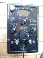
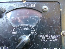
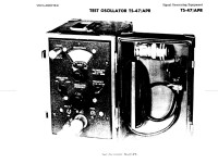
Test Oscillator TS-47/APR - FCI - U.S.A. - 1944 |
 |
|
|
 |
Italiano
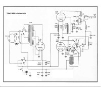
Schema elettrico |
|
|
The
instrument used 3 valves: two 9002, seven-pin miniature-type VHF vacuum
triodes (which since 1943 had replaced the 955-type acorn valves), and a
6X5 biplate rectifier with octal socket. |
|||
 |
 |
 |
 |
 |
 |
 |
 |
|
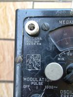
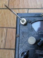
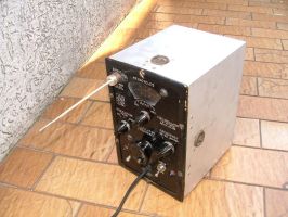
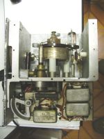
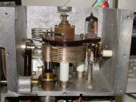
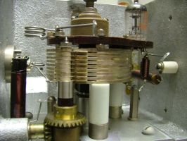
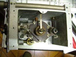
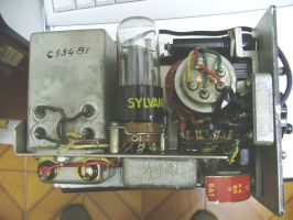
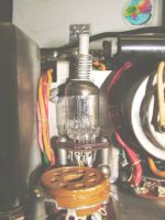
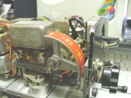
Questo oscillatore VHF e UHF veniva utilizzato dall'esercito e dalla marina USA per testare e calibrare vari ricevitori RCM (Contromisure Elettroniche). La copertura di frequenza era da 40 a 500 MHz in due gamme: 40-115 MHz e 115-500 MHz. L'uscita RF era disponibile sul connettore tipo N situato in alto a sinistra del pannello frontale. Il contatto centrale del connettore poteva inoltre essere esteso e funzionare come un'antenna ad asta. L'uscita a RF era di 3 mW nella banda da 40 a 400 MHz e di 1 mW da 400 a 500 MHz. Il segnale RF poteva essere sinusoidale o modulato con segnale di Bassa frequenza di 1000 Hz. La profonditą di modulazione poteva essere al 50% o con impulsi di 70 ms di durata e con una ripetizione di 500 impulsi al secondo. L'alimentazione dello strumento poteva essere fornita da batterie: una da 6,3 Vdc 550 mA per i filamenti e una da 225 Vdc 20 mA per l'anodica, oppure tramite rete elettrica AC selezionabile da 80, 115 e 230 Vac con frequenza da 50 a 2600 Hz. Lo strumento utilizzava 3 valvole: due 9002, triodi a vuoto VHF tipo miniatura a sette piedini (che dal 1943 avevano sostituito le valvole a ghianda tipo 955), e una 6X5 raddrizzatrice biplacca con zoccolo octal. © IK3HIA, 2005 |
|||
 |
 |
 |
 |
 |
 |
 |
 |
|
Torna a
inizio pagina
|
|||
| Return to IK3HIA home page | Return to Instruments page |