|
|
R.F. Signal
Generator SG8 - USA - 1951 - Repair - |
|
|
|
R.F. Signal
Generator SG8 - USA - 1951 - Repair - |
|
 English
 |
 |
Italiano
Schemi elettrici Manuale Heathkit |
|
 |
 |
 |
 |
|
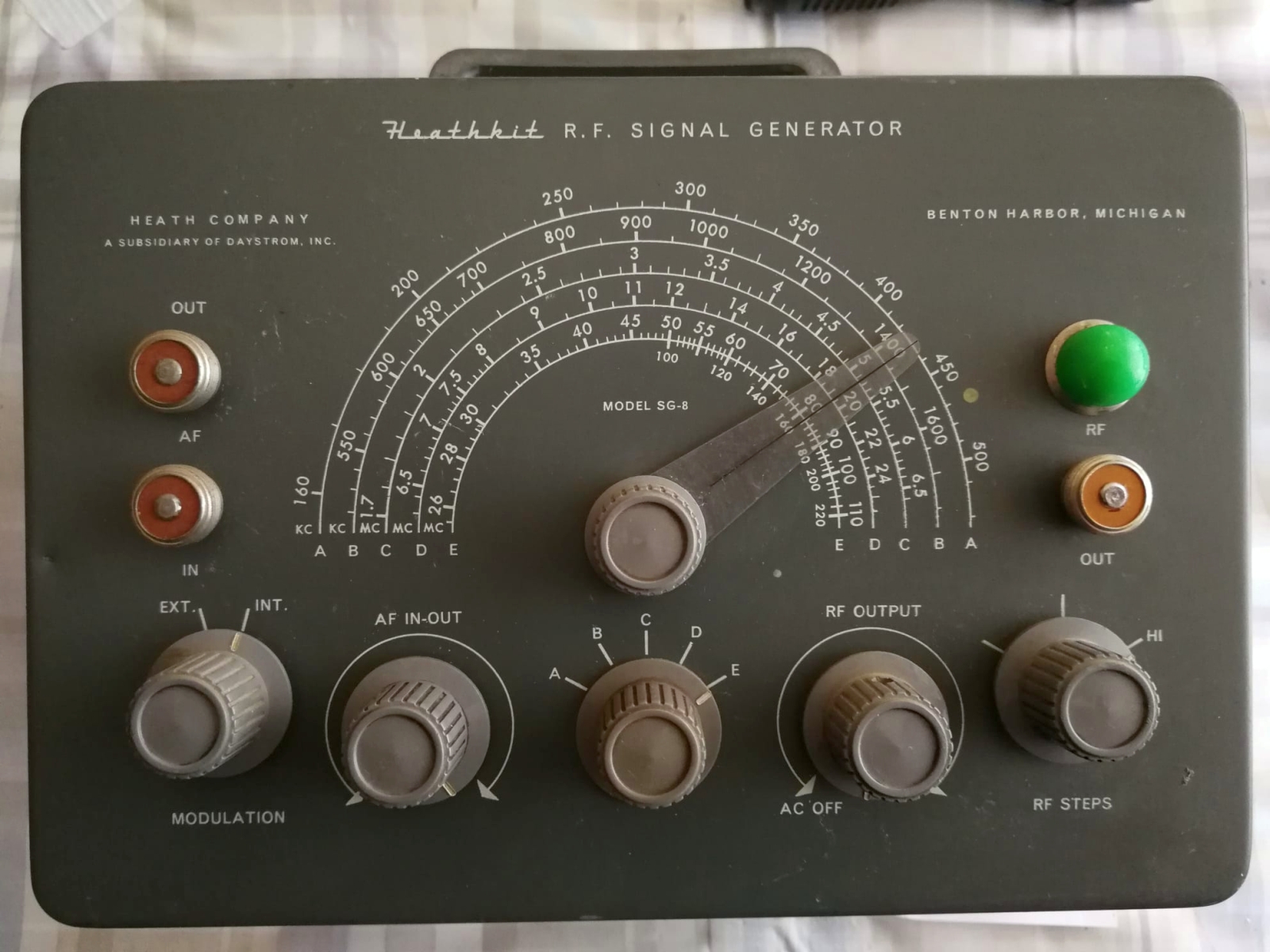
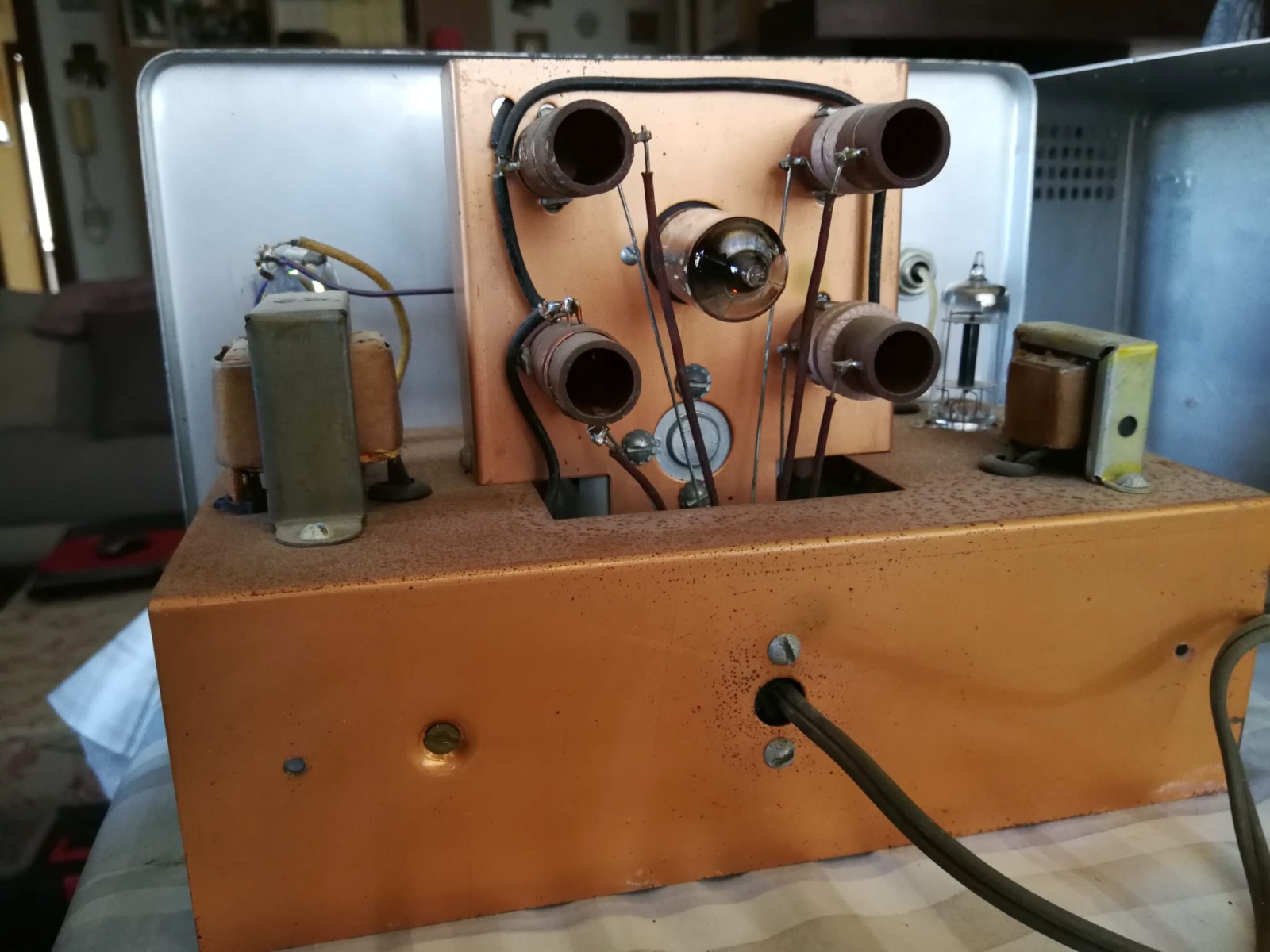
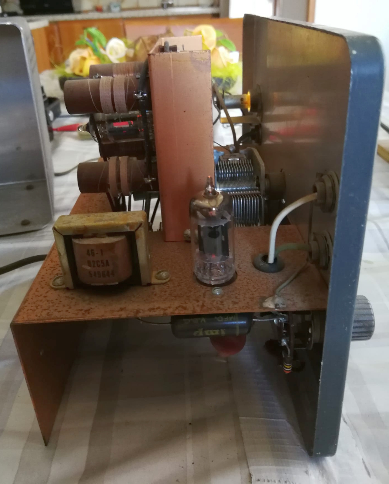
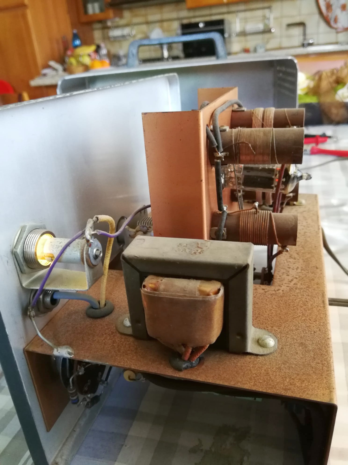
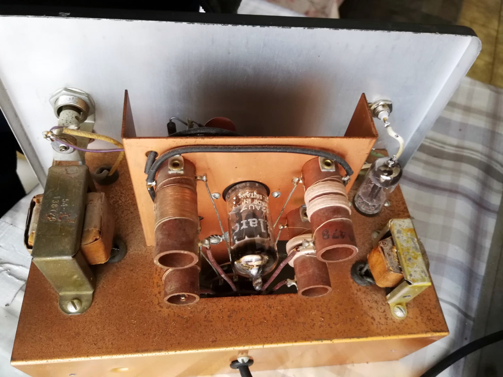
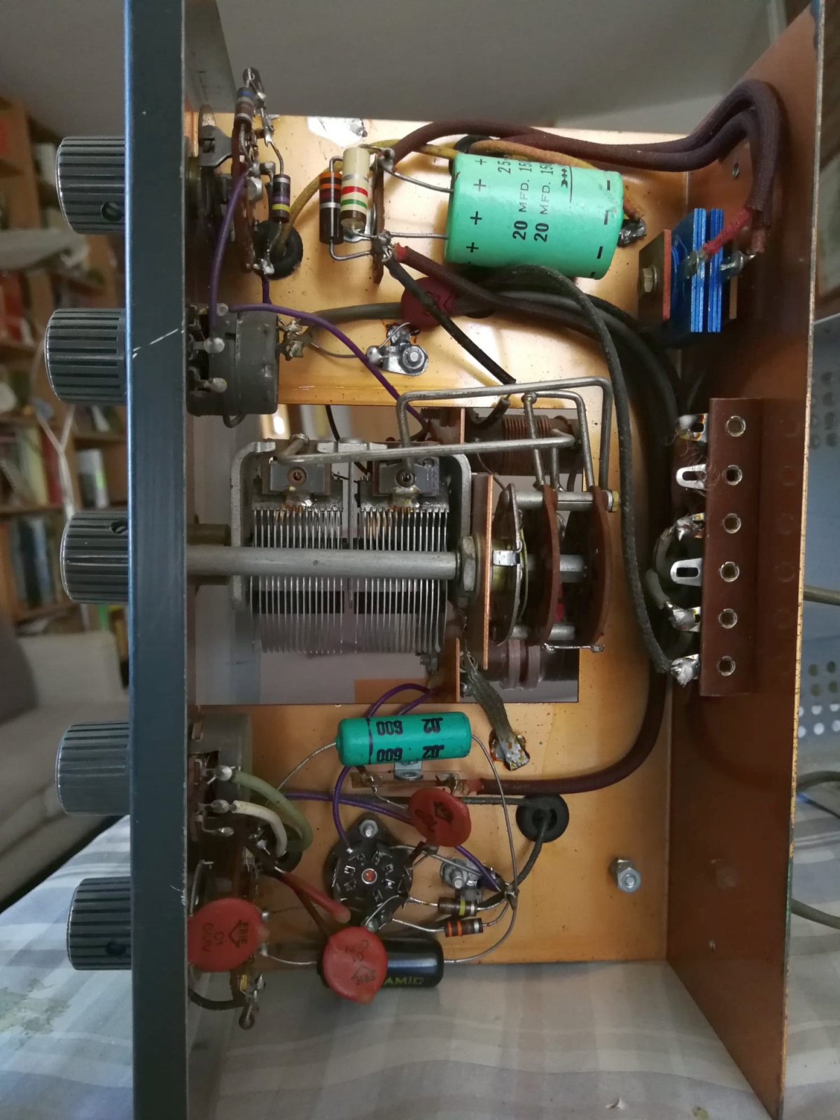
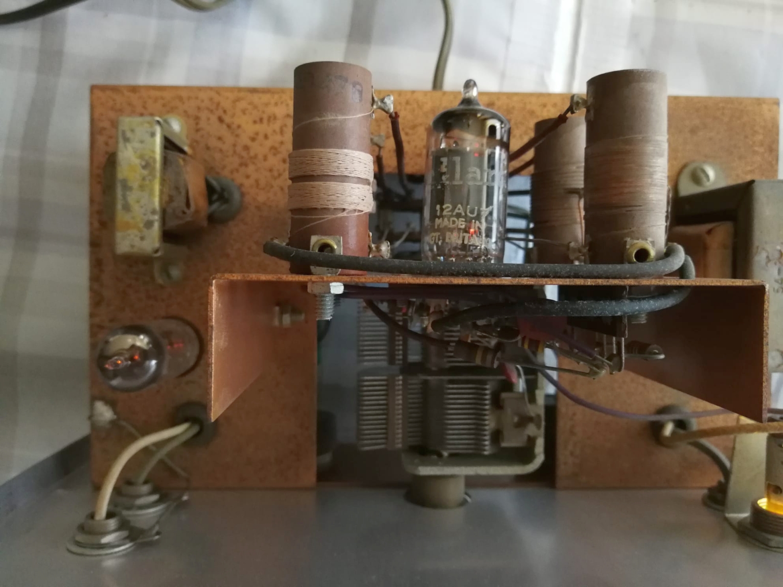
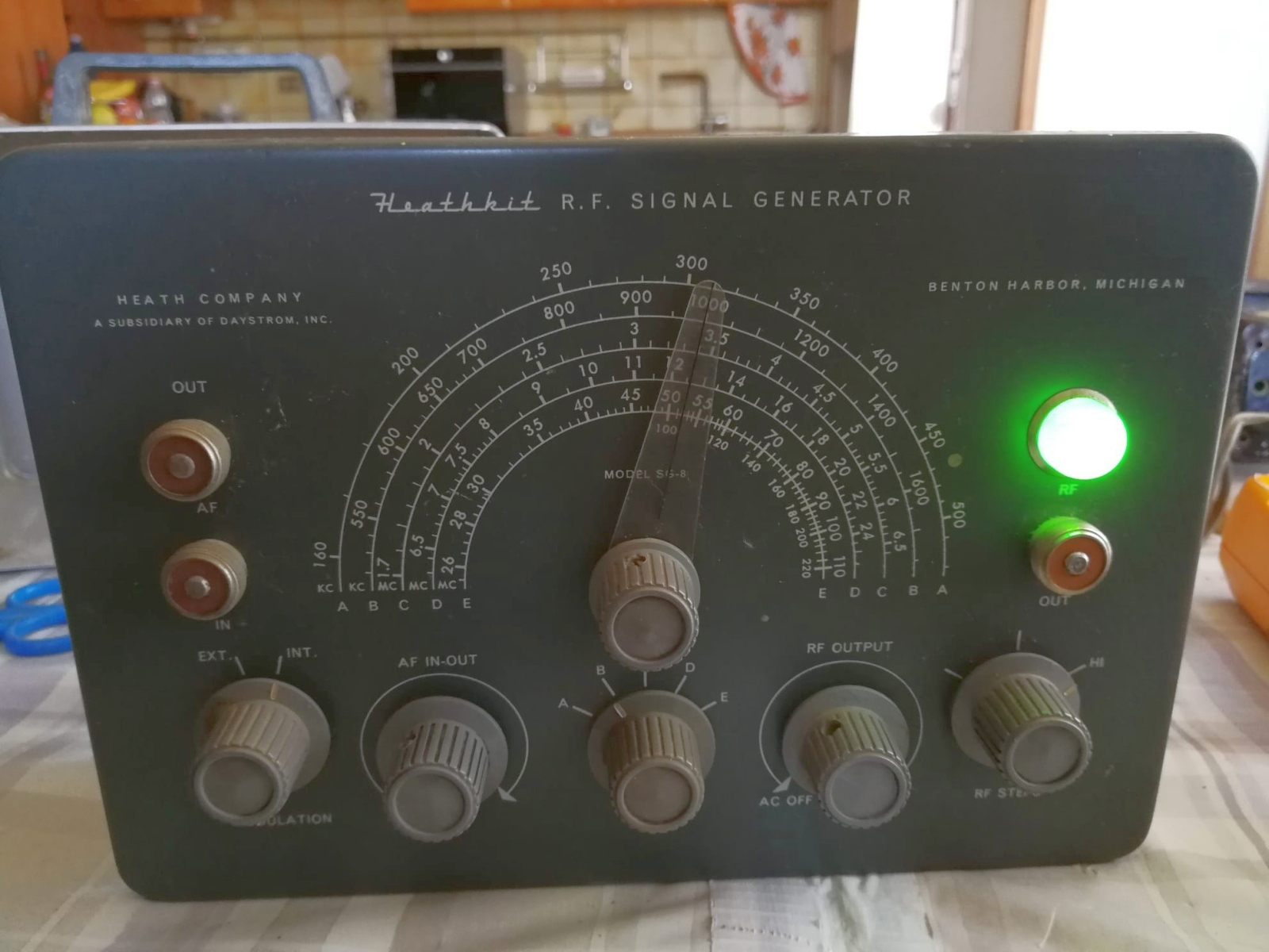
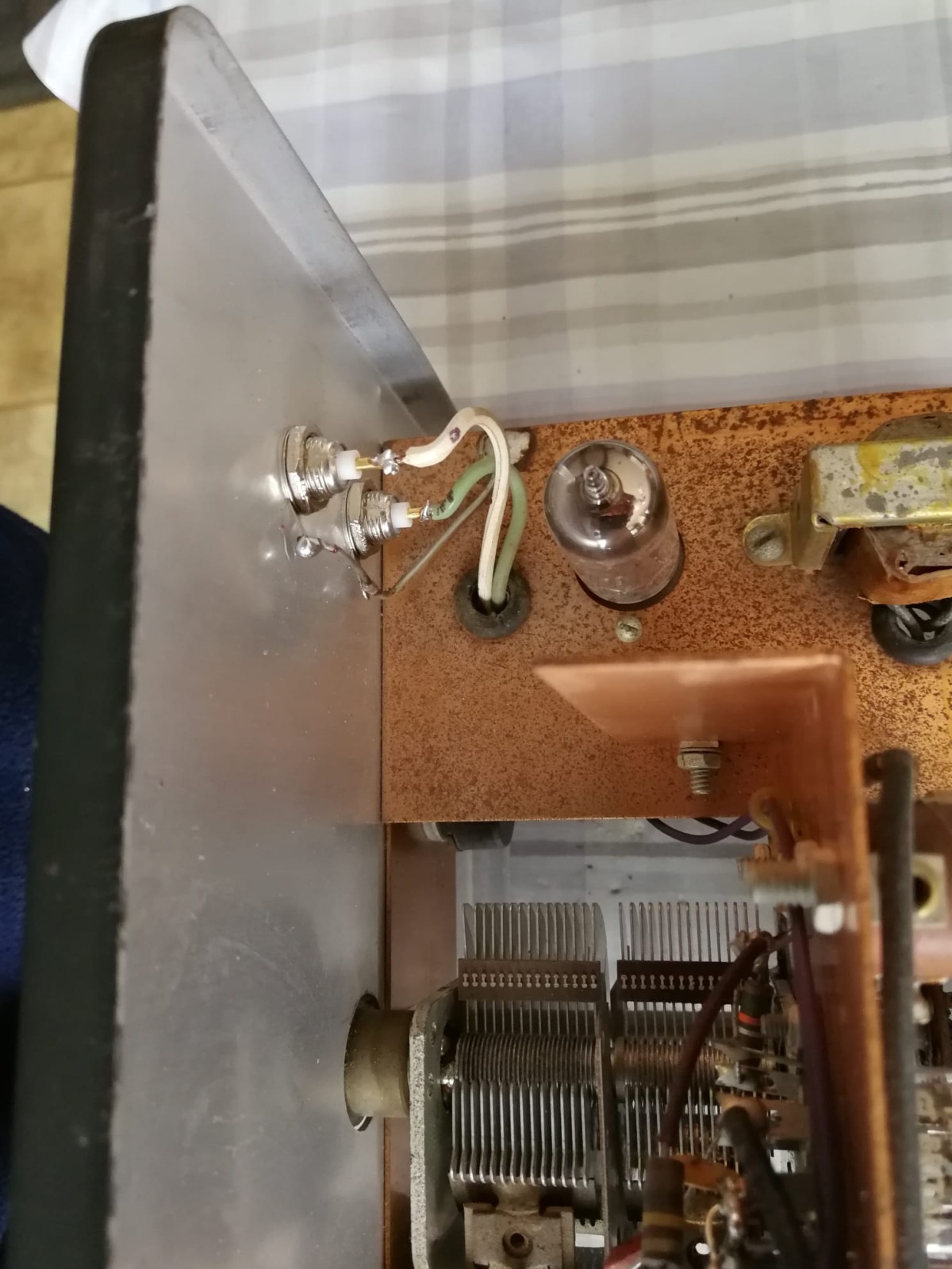
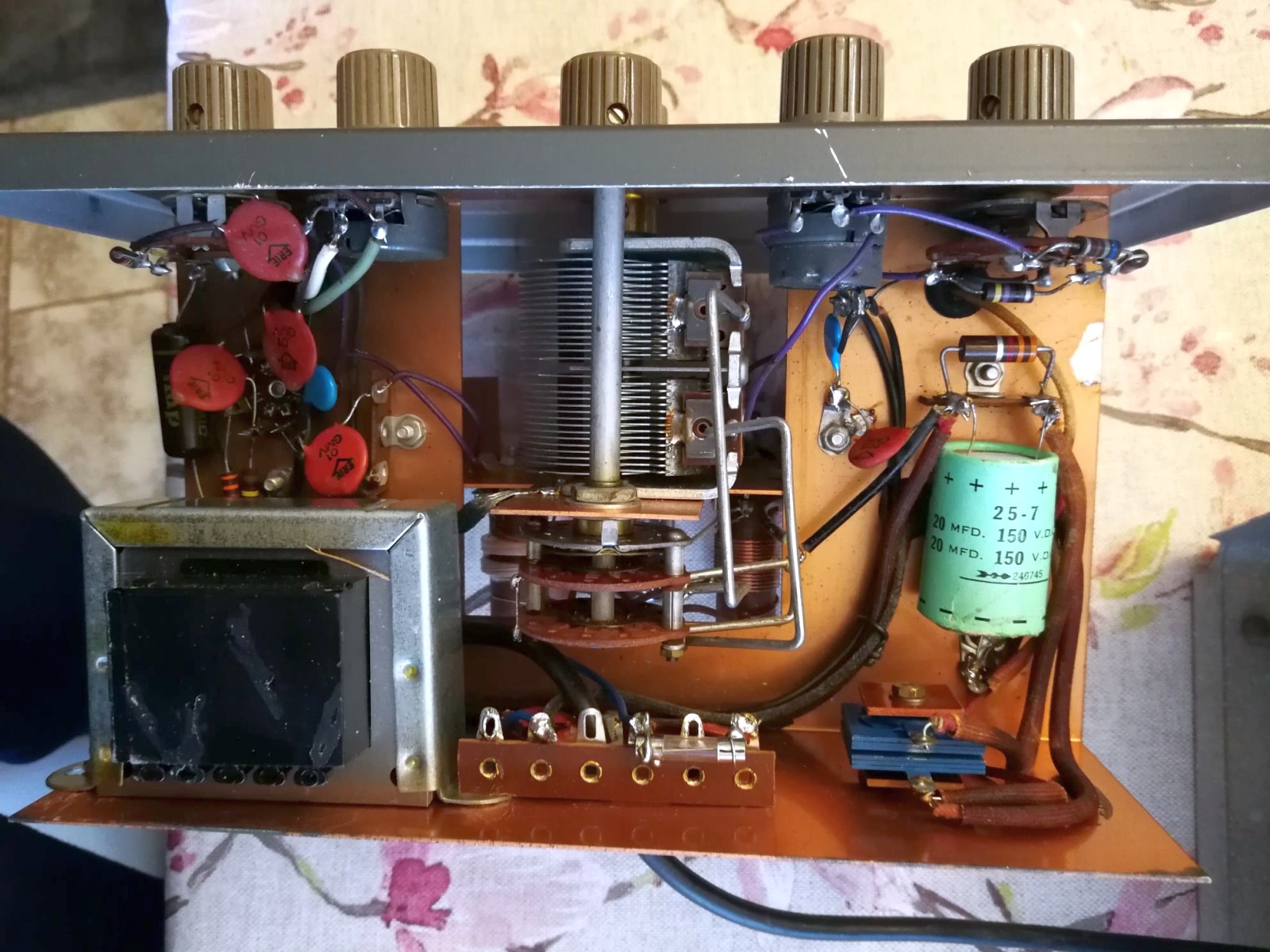
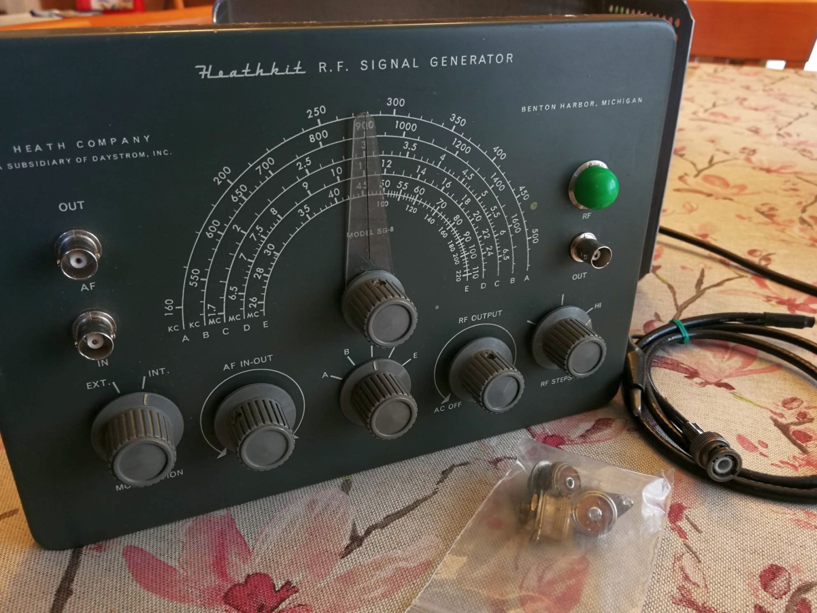
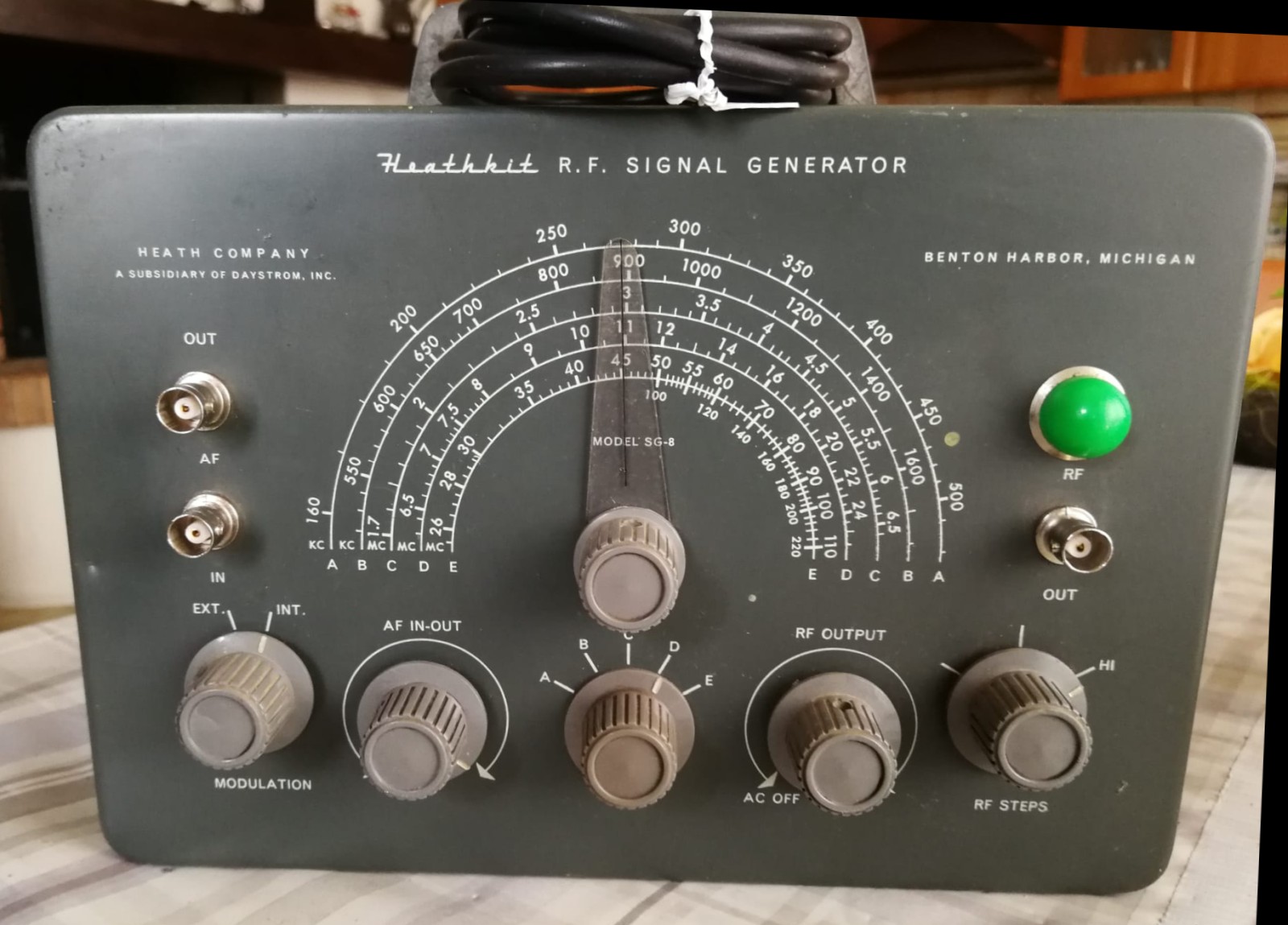
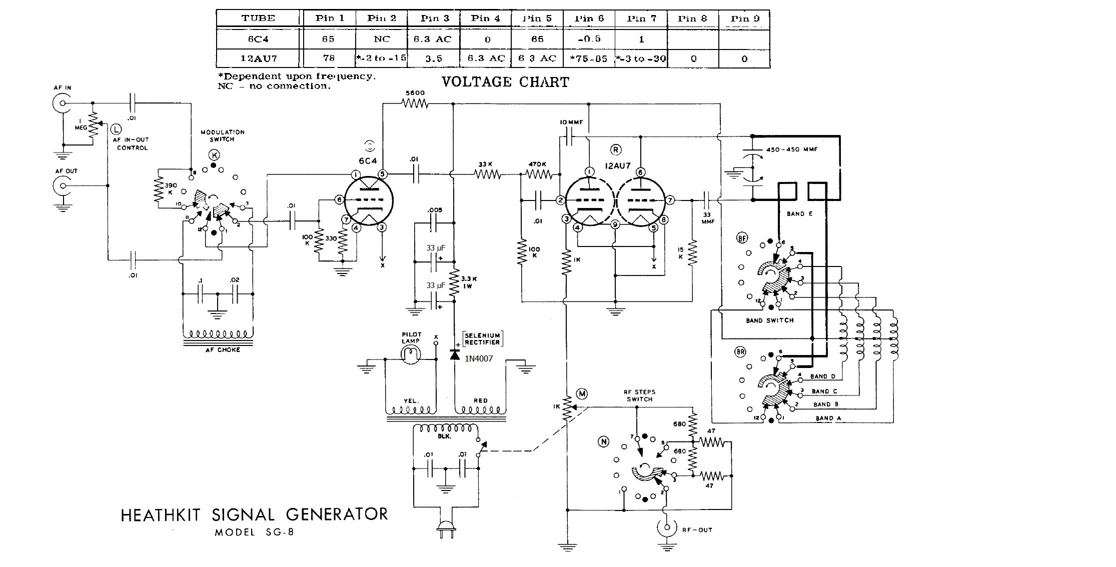
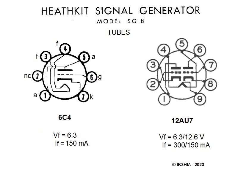
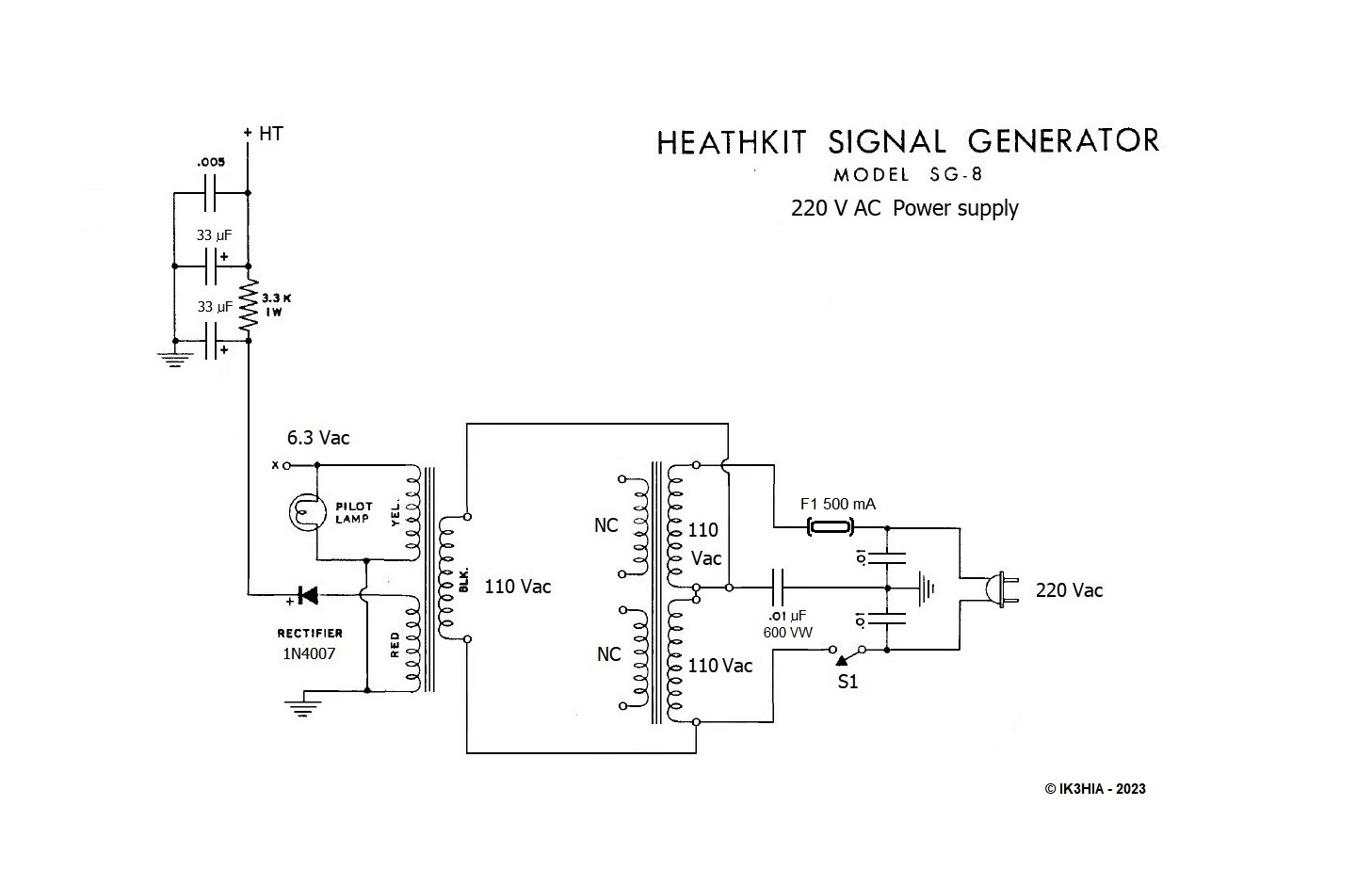
Tramite un autotrasformatore mi sono procurato i 110 Vac necessari senza preoccuparmi dei dei 60 Hz (per esperienza so che le apparecchiature USA funzionano bene anche con i 50 Hz della nostra rete elettrica) e dopo aver impostato la frequenza di 1000 Kc (banda B) sulla scala dell'SG8 ho pulito i contatti ossidati della spina elettrica e l'ho collegata ai 110 Vac. Con mia grande sorpresa la grossa lampada a spia con luce verde dell'apparecchio si è accesa senza senza accompagnamento di sintomi preoccupanti come sibili, scoppi o fumate. Vicino al generatore avevo posizionato un ricevitore Tecsun PL-600 sintonizzato in Onde Medie sui 1000 KHz. Il mio sbalordimento è aumentato a dismisura quando in corrispondenza della frequenza di 1 MHz del display del moderno ricevitore il segnale radio del generatore arrivava a fondo scala e dall'altoparlante del PL-600 proveniva l'inconfondibile modulazione a 400 Hz. Notare bene che non avevo collegato nessun filo tra generatore e ricevitore. Non ero in possesso di un cavetto dotato del connettore Amphenol 2501F necessario per interfacciarsi con i bocchettoni dell'SG8, ma senza il cabinet protettivo le onde radio arrivavano bene tanto da far schizzare a fondo scala lo s-meter digitale del ricevitore di Hong Kong. La modulazione a 400 Hz però non era molto forte e nel sottofondo si sentiva l'inconfondibile ronzio dei 50 Hz della nostra rete elettrica, perciò ho spento il tutto e ho iniziato il lavoro di restauro. La prima parte da restaurare era l'alimentatore. Con il tester ho misurato la tensione anodica prima e dopo il raddrizzatore al selenio. Il vecchio elemento "funzionava" ancora ma la sua efficienza si era deteriorata e lasciava passare l'alternata. Soluzione: bisognava sostituire il vecchio raddrizzatore al selenio con un moderno diodo 1N4007. Ovviamente il diodo al silicio aveva una resistenza interna più bassa e pertanto avrei dovuto ritoccare il valore della resistenza di filtraggio del P greco. In precedenza però, per sopperire all'inefficienza del raddrizzatore, qualcuno aveva aggiunto una resistenza da 1500 Ohm in parallelo a quella da 3300 Ω originale del filtro. Per salvare l'apparenza "vintage" ho lasciato al suo posto il vecchio raddrizzatore e ho "nascosto" il piccolo 1N4007 dentro la guaina sterling del cavo che proveniva dal secondario del trasformatore, poi ho tolto la resistenza aggiunta. Il condensatore elettrolitico doppio da 20 + 20 μF magari poteva ancora funzionare, ma visto che c'ero ho preferito sostituirlo con due condensatori più recenti da 33 μF 200 VL che essendo più piccoli sono riuscito a far entrare nell'involucro di cartone del vecchio condensatore. Anche in tal caso le "apparenze" erano salve. Ho riacceso il tutto e con il tester ho verificato le tensioni: sul catodo del diodo c'erano 110 V continui che scendevano a 95 dopo la resistenza di filtro. Una prova con il Tecsun sui 3 MHz (gamma C) mi confermava il buon funzionamento e l'accuratezza di taratura, il livello di modulazione a 400 Hz invece rimaneva ancora basso. Dopo avere esaminato lo schema, ho provato a collegare provvisoriamente una capacità da 0.01 Kpf in parallelo al condensatore da 150 MMF (1 MMF equivale a 1 pF) che porta la frequenza audio al piedino 2 della 12AU7. La modulazione a 400 Hz adesso era forte, così ho saldato il nuovo condensatore ceramico al posto di quello vecchio. Il lavoro era quasi concluso, rimaneva solo da risolvere il problema del cavetto di collegamento. Oggigiorno i connettori Amphenol 2501F necessari per collegare gli Amphenol 75-PC1M presenti sul pannello dell'SG8 sono irrintracciabili, perciò ho smontato i tre vecchi 75-PC1M e li ho sostituiti con altrettanti BNC da pannello. I connettori originali li ho infilati in un sacchettino di plastica e li ho lasciati dentro il generatore, così che magari un domani qualcuno avrebbe potuto potuto facilmente ripristinare l'aspetto originale. Di sonde con cavo coassiale intestato con BNC maschio da una parte e due coccodrilli dall'altra ne ho parecchie, così adesso potevo utilizzare il vecchio generatore per allineare i circuiti delle vecchie radio a valvole e a transistor che mi diletto a restaurare. Per completare l'opera e per poter utilizzare il generatore senza rischiare di bruciarlo dimenticando di collegarlo ogni volta a un autotrasformatore capace di fornire 110 o 120 Vac, mi sono procurato un trasformatore da 25 VA con primario 115 + 115 Vac e con dimensioni tali da poter essere alloggiato all'interno dello strumento. Il trasformatore con doppio primario funge da autotrasformatore e fornisce la giusta tensione alternata a 115 Vac per alimentare generatore. Ho spostato i fili dell'interruttore sul primario del nuovo trasformatore e come si evince dallo schema ho aggiunto al circuito un fusibile da 500 mA e un condensatore da 0.01 μF 600V. © IK3HIA - 2023 |
|||
 |
 |
 |
 |
|
As
soon as the sample arrived in my possession I removed the generator from
the aluminum cabinet and inspected the electronic circuit. All the
components looked like the original ones and appeared intact. At that
point I couldn't help but feed it and check if it could still work after
so many years. Using an autotransformer, I obtained the necessary 110 Vac without worrying about the 60 Hz (from experience I know that US equipment also works well with the 50 Hz of our net) and after having set the frequency of 1000 Kc (band B) on the scale of the SG8 I cleaned the oxidized contacts of the electric plug and connected it to 110 Vac. To my great surprise, the large green light of the device came on without accompanying worrying symptoms such as hissing, banging or smoke. Near the generator I had positioned a Tecsun PL-600 receiver tuned in Medium Waves on 1000 KHz. My amazement increased dramatically when at the 1 MHz display frequency of the modern receiver the radio signal from the generator reached full scale and the unmistakable 400 Hz modulation came from the PL-600 loudspeaker. Note well that I had not connected any wires between generator and receiver. I didn't have a cable equipped with the Amphenol 2501F connector needed to interface with the SG8's ports, but without the protective cabinet the radio waves arrived so well that the digital s-meter of the Hong Kong receiver shot to full scale. However, the 400Hz modulation wasn't very strong and there was the unmistakable 50Hz hum of our mains electricity in the background, so I turned it all off and started the restoration work. The first part to restore was the power supply. With the tester I measured the anode voltage before and after the selenium rectifier. The old element still "worked" but its efficiency had deteriorated and it let the AC through. Solution: the old selenium rectifier had to be replaced with a modern 1N4007 diode. Obviously the silicon diode had a lower internal resistance and therefore I would have had to adjust the value of the filtering resistance of the Greek P. Previously however, to make up for the inefficiency of the rectifier, someone had added a 1500 Ohm resistor in parallel to the original 3300 Ω one of the filter. To save the "vintage" appearance I left the old rectifier in place and I "hid" the small 1N4007 inside the sterling sheath of the cable that came from the transformer secondary, then I removed the added resistance. The 20 + 20 μF double electrolytic capacitor could still work, but since I was there I preferred to replace it with two more recent 33 μF 200 VL capacitors which, being smaller, I managed to fit into the cardboard casing of the old capacitor . Even in this case the "appearances" were safe. I turned everything back on and with the tester I checked the voltages: on the cathode of the diode there were 110 V continuous which dropped to 95 after the filter resistance. A test with the Tecsun on 3 MHz (range C) confirmed the good functioning and the calibration accuracy, the modulation level at 400 Hz instead still remained low. After looking at the schematic, I tried tentatively connecting a 0.01Kpf capacitor in parallel with the 150MMF capacitor (1MMF equals 1pF) which carries the audio frequency to pin 2 of the 12AU7. The 400Hz modulation was now strong, so I soldered the new ceramic capacitor in place of the old one. The work was almost finished, the only thing left to solve was the connection cable problem. Nowadays the Amphenol 2501F connectors needed to connect the Amphenol 75-PC1Ms on the SG8 panel are untraceable, so I disassembled the three old 75-PC1Ms and replaced them with as many panel BNCs. I slipped the original connectors into a plastic bag and left them inside the generator, so that maybe one day someone could easily restore the original look. I have several probes with coaxial cable headed with a male BNC on one side and two crocodiles on the other, so now I could use the old generator to align the circuits of the old tube and transistor radios that I enjoy restoring. To complete the work and to be able to use the generator without risking burning it by forgetting to connect it each time to an autotransformer capable of supplying 110 or 120 Vac, I got myself a 25 VA transformer with 115 + 115 Vac primary and with dimensions such as to be able to be housed inside the instrument. The transformer with double primary acts as an autotransformer and supplies the right alternating voltage at 115 Vac to power the generator. I moved the switch wires to the primary of the new transformer and as shown in the diagram I added a 500 mA fuse and a 0.01 μF 600 V capacitor to the circuit. © IK3HIA - 2023 |
|||
 |
 |
 |
 |
 |
 |
 |
 |
|
|
|
Return to Instruments
page
|
